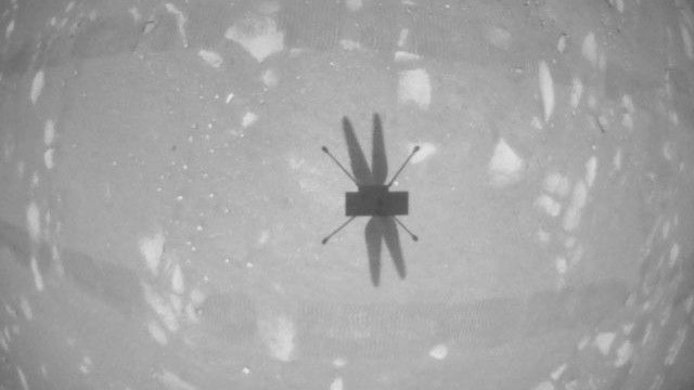
Before each of Ingenuity’s test flights, we upload instructions that describe precisely what the flight should look like. But when it comes time to fly, the helicopter is on its own and relies on a set of flight control algorithms that we developed here on Earth before Ingenuity was even launched to Mars.
To develop those algorithms, we performed detailed modeling and computer simulation in order to understand how a helicopter would behave in a Martian environment. We followed that up with testing in a massive 25-meter-tall, 7.5-meter-diameter vacuum chamber here at JPL where we replicate the Martian atmosphere. But in all of that work, we could only approximate certain aspects of the environment. Now that Ingenuity is actually flying at Mars, we can begin to assess how things stack up against expectations. Here are some key aspects of the flight control system’s performance on Mars.
Takeoff
Unlike many consumer drones, Ingenuity is not controlled by changing the rotor speeds. Instead, we control our Mars Helicopter in the same manner as full-scale terrestrial helicopters: by changing the pitch angle of the blades, which affects the airfoil “angle of attack” and thereby determines how big a “bite” the blades take out of the air. The bigger the bite, the more lift (and drag) is produced. Like a traditional helicopter, we can change the pitch angle in two ways: by using “collective control,” which changes the blade pitch uniformly over the entire rotation of the blade, and by using “cyclic control,” which pitches the blade up on one side of the vehicle and down on the other.
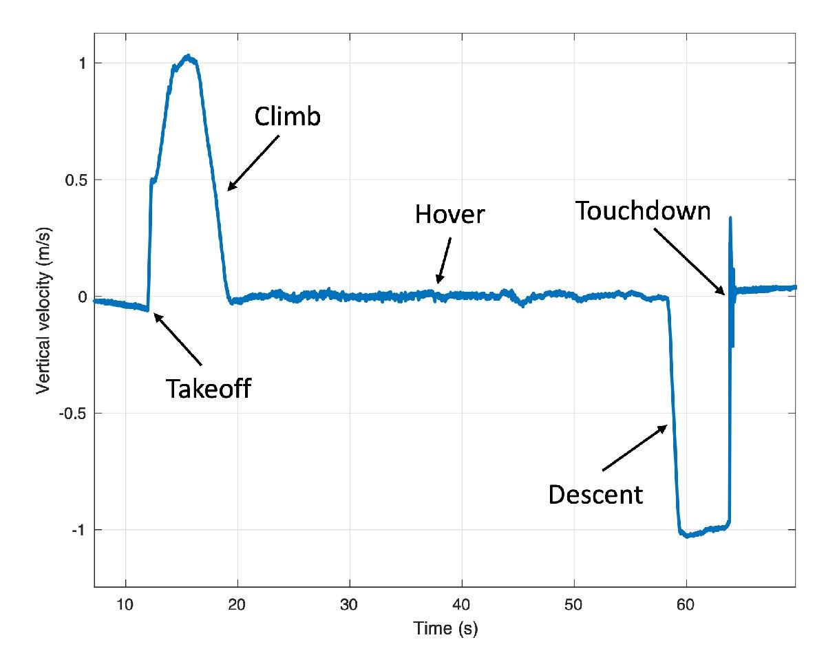
When Ingenuity takes off, the rotor is already spinning at the setpoint speed of 2,537 rpm. We take off with a sudden increase in collective control on both rotors, which causes the vehicle to “boost” off the ground. During this initial takeoff phase, we limit the control system to respond only to angular rates (how quickly the helicopter rotates or tilts). The reason for this is that we don’t want the control system to be fighting against the ground, possibly resulting in undefined behavior.
The initial takeoff phase lasts for only a split second; once the helicopter has climbed a mere 5 centimeters, the system asserts full control over the helicopter’s position, velocity, and attitude. At this point we’re accelerating toward a vertical climb rate of 1 meter per second.
To estimate our movements during flight, we use a set of sensors that include a laser rangefinder (for measuring altitude) and a camera. We don’t use those sensors until we reach 1 meter altitude out of concern that they might be obscured by dust near the ground. Instead, we initially rely only on an inertial measurement unit (IMU) that measures accelerations and angular rates, and we integrate those measurements to estimate our movements. This is a type of “dead reckoning” navigation – comparable to measuring how far you’ve walked by counting your steps. It’s not very accurate in the long run, but because Ingenuity takes only a couple of seconds to reach 1 meter, we can make it work.
One of the things we were curious about is how “confidently” Ingenuity would boost off the ground and reach that first threshold of 5 cm. Data from the first three flights shows that portion of the climb took about 0.25 seconds, which is very much in line with expectations and indicates that Ingenuity had no issue producing enough thrust on takeoff. During this initial boost, we expected to see a spike in the power required by the rotor system, and that is indeed what we observed. For example, the spike in Flight Two was about 310 watts (W) – well below the maximum capacity of our batteries, which can tolerate spikes as high as 510 W.
After takeoff, Ingenuity took about 2 seconds to reach the 1-meter altitude where it could start using its full suite of sensors. That being said, while we did see some faint dust in the images taken by the Perseverance rover (parked nearby) on takeoff, there was no indication flying dust or sand obscured the altimeter or camera, so our design appears to have erred on the cautious side in this regard (which is a good thing).
The moment the helicopter’s legs leave the ground, its motion starts to become affected by wind. These winds can cause the vehicle to momentarily roll (side to side) or pitch (forward or backward) on takeoff, until it has time to catch and correct itself. We were prepared for some significant roll/pitch angles on takeoff if winds were high at the ground level, but in Ingenuity’s three takeoffs so far, they have been limited to a couple of degrees only, making for nice, vertical takeoffs.
Hover
During hover phases of flight, we are attempting to maintain a constant altitude, heading, and position. In evaluating how well we are managing to achieve that, we are forced, for the most part, to rely on Ingenuity’s own estimates of what it was doing, as we have limited data establishing “ground truth.” Those estimates are subject to errors in navigation that will be covered in a separate post. But the steadiness of these estimates tells us a lot about how tightly the controller is able to hold the desired values.
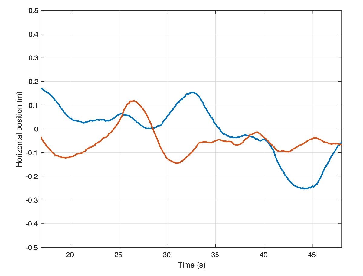
The data shows that we hold our altitude extremely well in hover, to within approximately 1 cm. We also hold the heading (which way we point) to within less than 1.5 degrees. For horizontal position, we’ve seen variations up to approximately 25 cm. Such variations are expected as the result of wind gusts.
So, what has the wind been like during our flights? Fortunately for us, the Perseverance rover carries the MEDA weather station. For Flight One, we have measurements from MEDA indicating winds of 4-6 meters per second from the east and southeast during most of the flight, gusting to 8 meters per second. Keep in mind that those measurements are made 1.5 meters above ground level, and the tendency is for winds to increase as you go from ground level up. We also have atmospheric density measurements at the time of Flight One, showing 0.0165 kilograms per cubic meter, or about 1.3% of Earth’s density at sea level. Using this information, we can assess the system’s performance in another important respect – namely, the control effort required to fly.
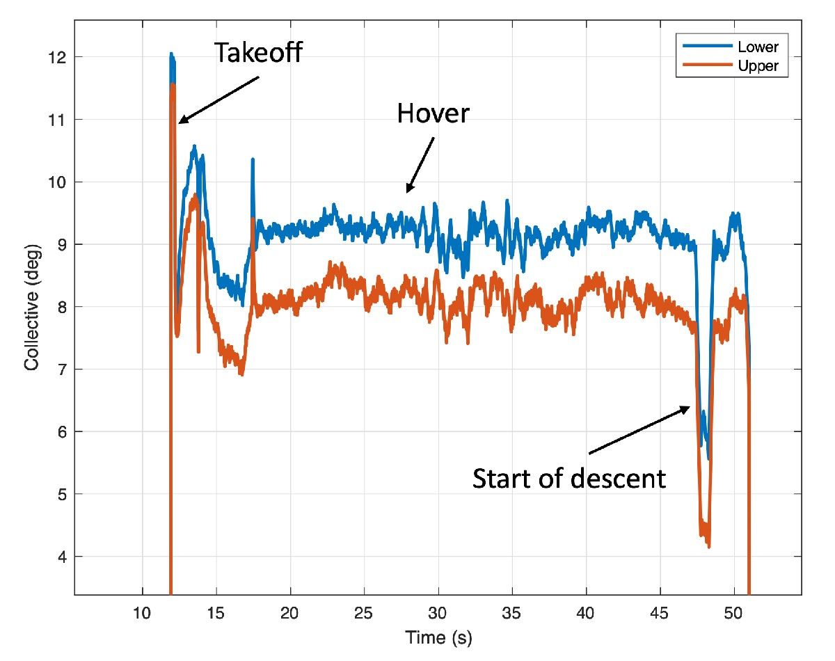
For the collective control (remember, that is the one that changes rotor blade pitch angle uniformly to affect helicopter’s thrust), we would like to see hover values roughly consistent with prior expectations. During Flight One, we hovered with around 9.2 degrees collective on the lower rotor and 8.2-degree collective on the upper (that’s the angle of the blade’s “chord line” – an imaginary line drawn from the leading edge to the trailing edge of the rotor blade – at ¾ of the rotor radius). Those values are 0.7-0.8 degrees lower than the trim values we anticipated (9.0 degree on the upper rotor and 9.9 degree on the lower rotor). But those trim values were tuned based on tests without wind at a somewhat different density/rotor speed combination, so this difference is not unexpected. Another indication that we are within our aerodynamic comfort zone is the electrical rotor power of around 210 W in hover, which is also right in the vicinity of what was expected. Taken together, the results indicate that we have good margin against “aerodynamic stall,” which is when the blade airfoil’s angle relative to the surrounding airflow is increased beyond the point where it can produce further increases in lift.
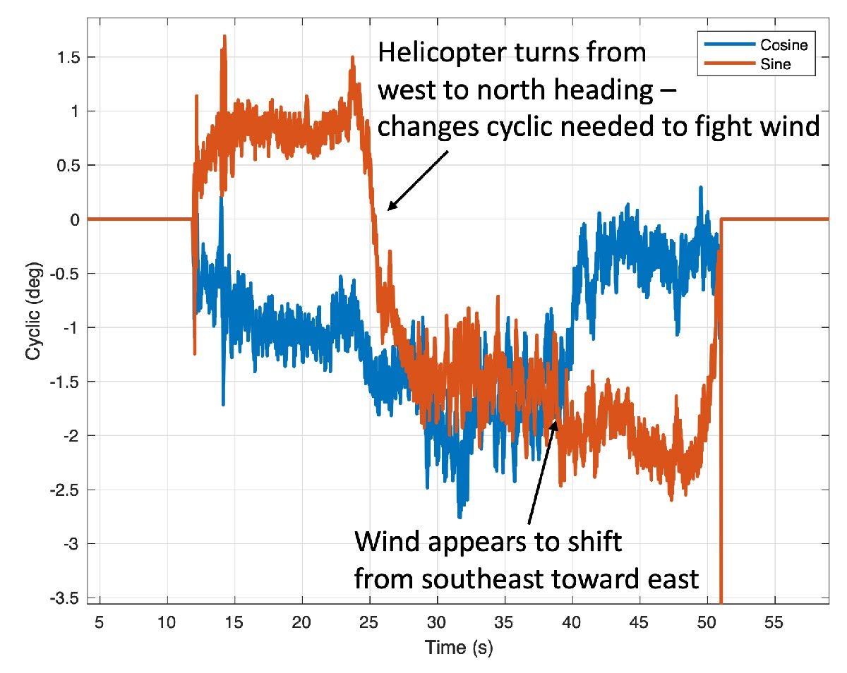
We also evaluate the cyclic control, which is used to create roll and pitch moments on the vehicle. We have seen relatively steady values in hover, generally of magnitude less than 3 degrees, which leaves ample margin against the upper limit of 10 degrees. The cyclic control inputs tell us a fair amount about the wind that the vehicle has to fight against. For example, for Flight One the cyclic control is consistent with winds from the east and southeast, which is in alignment with MEDA observations. The cyclic control effort also increases with altitude, which indicates that winds are getting higher further from the ground.
Landing
Landing is a particularly challenging part of any flight. Ingenuity lands by flying directly toward the ground and detecting when touchdown happens, but a number of events occur in rapid succession leading to touchdown. First, a steady descent rate of 1 meter per second is established. Then, once the vehicle estimates that the legs are within 1 meter of the ground, the algorithms stop using the navigation camera and altimeter for estimation, relying on the IMU in the same way as on takeoff. As with takeoff, this avoids dust obscuration, but it also serves another purpose -- by relying only on the IMU, we expect to have a very smooth and continuous estimate of our vertical velocity, which is important in order to avoid detecting touchdown prematurely.
About half a second after the switch to IMU-only, when the legs are estimated to be within 0.5 meters of the ground, the touchdown detection is armed. Ingenuity will now consider touchdown to have occurred as soon as the descent velocity drops by 25 centimeters per second or more. Once Ingenuity meets the ground, that drop in descent velocity happens rapidly. At that point, the flight control system stops trying to control the motion of the helicopter and commands the collective control to the lowest possible blade pitch in order to produce close to zero thrust. The system then waits 3 seconds to ensure the helicopter has settled on the ground before spinning down the rotors.
People have asked why we contact the ground at the relatively high speed of 1 meter per second. There are multiple reasons for this. First, it reduces the dead-reckoning time that we need to spend without using the camera and altimeter; second, it reduces the time spent in “ground effect,” where the vehicle dynamics are less well-characterized; and third, it makes it easier to detect that we’ve touched down (because the velocity change is clearly sufficient for detection). What makes this strategy possible is the landing gear design which helps prevent the vehicle from bouncing on landing.
Any touchdown detection algorithm of this kind has to strike a balance between two potential pitfalls: (1) detecting touchdown too early (thereby dropping to the ground from the air) and (2) not detecting touchdown soon enough (which would cause the helicopter to keep trying to fly after coming in contact with the ground). Data from Ingenuity’s flights on Mars show that we were not in danger of either of these scenarios. During descent, Ingenuity has maintained its vertical velocity to within approximately 4 cm per second, and it has detected the necessary 25 cm per second drop within approximately 30 milliseconds of touchdown.
As we continue with our flights on Mars, we will keep digging deeper into the data to understand the various subtleties that may exist and would be useful in the design of future aerial explorers. But what we can already say is: Ingenuity has met or exceeded our flight performance expectations.

