


![Request for Information – Potential [Placeholder for Prize]](https://assets.science.nasa.gov/dynamicimage/assets/science/missions/a-step/FFR_Earth_Background_20251120%20.png?w=1024)


TO2-IM
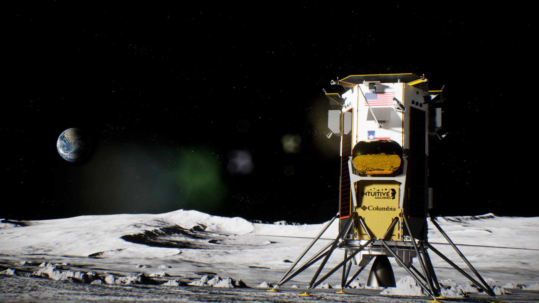
Intuitive Machines's Nova-C lunar lander launched on February 15, 2024 to deliver 6 NASA CLPS science payloads to Malapert A. It landed on February 22, 2024. Click here for more information.
Lunar Node 1 Navigation Demonstrator (LN-1)
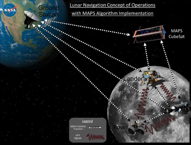
Summary: CubeSat-sized flight hardware experiment that integrates navigation and communication functionality for autonomous navigation to support future surface and orbital operations. LN-1 uses Multi-spacecraft Autonomous Positioning System (MAPS) algorithms and standard GPS-like navigation signal (specifically, one-way pseudonoise ranging codes), which is akin to using GPS on Earth. Through installation of S-band beacons on the surface, this local navigation network would act like a series of lighthouses and help guide incoming vehicles to land with high precision, departing vehicles to insert themselves into an accurate orbit and reduce their fuel requirements, orbital vehicles maintain knowledge of their orbit, and direct autonomous vehicles across a planetary surface. These beacons could be deployed as hosted payloads on mobile and static assets or as independent infrastructure.
Type of Instrument: Navigation beacon
Key Measurement: Transmits multiple types of radio signals that can be used to measure distance
Task Order: CLPS TO2-IM (2/20C/OP)
Lead Development Organization: NASA MSFC
Payload PI: Dr. Evan Anzalone
Stereo Cameras for Lunar Plume-Surface Studies (SCALPSS)


Summary: SCALPSS will use four cameras (two stereo pairs) that will capture video and still image data of the lander’s descent engine plume of dust as the plume starts to impact the lunar surface until after engine shut off. Data will be used to assess the effect of the engine plumes on the landing site, the landing vehicle, and nearby assets and sites, resulting in better predictive capabilities to lower risk and ensure landing success, which is critical for future lunar and Mars vehicle designs. SCALPSS leverages camera technology used on the Mars 2020 rover.
Type of Instrument: Cameras
Key Measurement: video and still images - validation data for plume-surface interaction analysis. Returns data for the onset, rate, shape, and volume of the plume crater formation.
Task Order: CLPS TO2-IM (2/20C/OP)
Lead Development Organization: NASA LaRC
Payload PI: Michelle Munk
Radio-wave Observations at the Lunar Surface of the photo Electron Sheath (ROLSES)
Summary: Just above the surface of the Moon is a very, very thin layer (or sheath) of electrons that come in part from electrons that are knocked out of individual lunar dust/regolith molecules by photons of UV light from the Sun during the daytime, and in part from the solar wind (electrons and ions). At twilight, this can charge lunar dust, so it levitates and creates a hazy horizon. The ROLSES payload will employ a low-frequency radio receiver system to determine the density of this electron sheath. The instrument is a low-frequency radio spectrometer to provide radio spectra (from 10 kHz - 10 MHz, or possibly 30 MHz) ~0-2 m above the lunar surface, using antennas at 1 m and 2 m above the surface. ROLSES will also detect solar radio bursts, radio emissions from Jupiter, dust impacting the surface of the moon, and how radio noisy Earth is. These measurements will aid future exploration missions by demonstrating the plasma environment astronauts or other exploration systems will encounter on the Moon and a baseline for a sensitive future radio observatory on the Moon.
Type of Instrument: Low-frequency radio astronomy receiver system
Key Measurement: Electron sheath density and scale height; radio emissions from the Earth, Sun, and planets; dust impacts
Task Order: CLPS TO2-IM (2/20C/OP)
Lead Development Organization: NASA GSFC
Payload PI: Dr. Nat Gopalswamy
Navigation Doppler Lidar for Precise Velocity and Range Sensing (NDL)
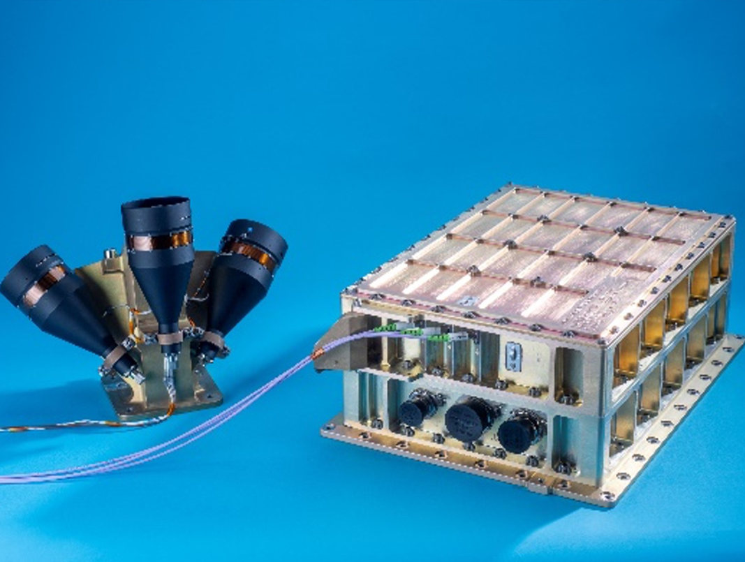
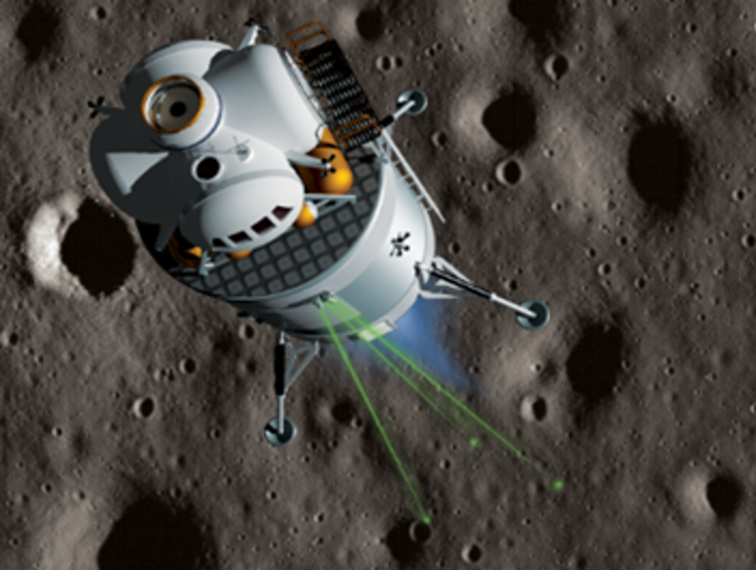
Summary: NDL is a LIDAR-based (Light Detection and Ranging) descent and landing sensor. This instrument operates on the same principles of radar but uses pulses of light from a laser instead of radio waves. NDL measures vehicle velocity (speed and direction) and altitude (distance to ground) with high precision during descent from over 5 km altitude to touchdown. NDL consists of a chassis containing electronics and photonics and an optical head with three small telescopes for transmitting laser beams and collecting the returns from the ground. The chassis and the optical head are connected by 3 fiber-optic cables. NDL measurements allow for precision navigation to the designated landing location and enable a tightly controlled soft touchdown on the surface of the Moon and other planetary bodies.
Type of Instrument: Guidance and navigation sensor
Key Measurement: Velocity (speed and direction) and altitude (distance to ground) from 5 km altitude
Task Order: CLPS TO2-IM (2/20C/OP)
Lead Development Organization: NASA LaRC
Payload PI: Dr. Farzin Amzajerdian
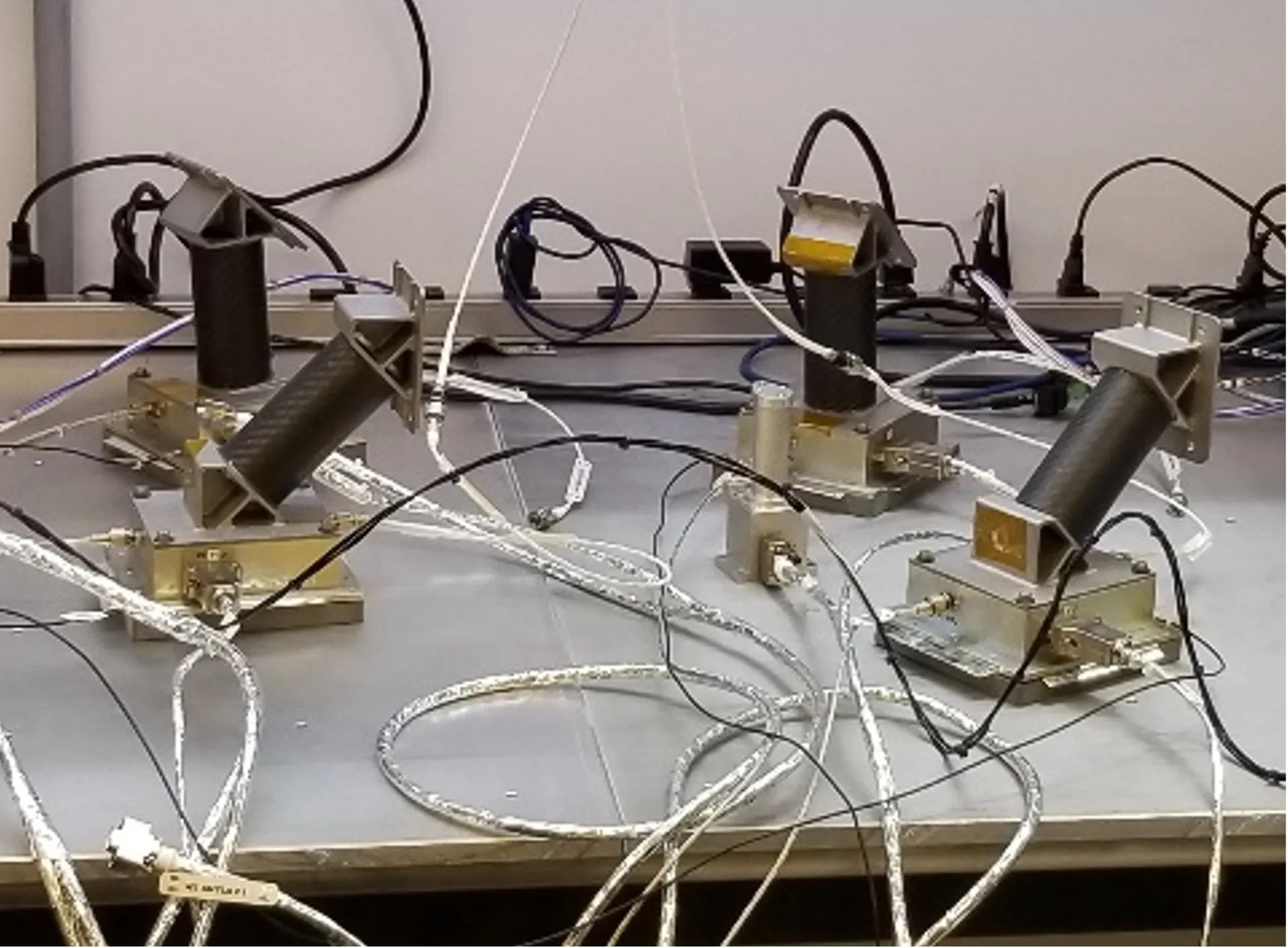
Radio Frequency Mass Gauge (RFMG)
Summary: Antennae that are installed inside the liquid oxygen and liquid methane fuel tanks of the lander to gauge the quantity of liquid fuel as it is used. A goal of long-range space missions in the future is the ability to use cryogenic propellants.
Type of Instrument: Low-gravity propellant quantity gauge
Key Measurement: The mass of fuel in the lander’s fuel tanks
Task Order: CLPS TO2-IM (2/20C/OP)
Lead Development Organization: NASA GRC
Payload PI: Dr. Greg Zimmerli
Laser Retroreflector (LRA)
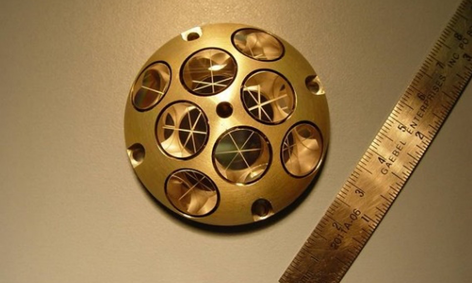
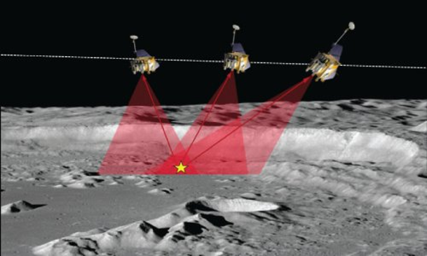
Summary: A retroreflector bounces any light that shines on it directly backward (180 degrees from the incoming light). The LRA is a collection of eight of these, each a 1.25-cm diameter glass corner cube prism, all embedded in an aluminum hemisphere (painted gold as shown here) and is mounted to the lander deck. This design ensures that the LRA can retroreflect (i.e., bounce) laser light from other orbiting and landing spacecraft over a wide range of incoming directions and efficiently retroreflect the laser signal directly back at the originating spacecraft. This enables precision laser ranging, which is a measurement of the distance between the orbiting or landing spacecraft to the LRA on the lander. The LRA is a passive optical instrument and will function as a permanent fiducial (i.e., location) marker on the Moon for decades to come. (Note: this LRA design is too small for laser ranging from Earth).
Type of Instrument: Passive optical device that reflects laser light directly backward (for laser ranging)
Key Measurement: Precise distances
Task Order: CLPS TO2-IM (2/20C/OP), TO2-AB, TO20A-VIPER, and PRIME-1
Lead Development Organization: NASA GSFC
Payload PI: Dr. Xiaoli Sun