


The Science
Science Background
Over the past three decades, much advancement has been made in Earth-based laboratories in reducing the temperature of Bose Einstein Condensate (BEC) to below the condensate temperature. Inherent to these experiments is the application of an intense magneto-optical trap to hold the atoms in place to obtain the required cooling, due to the pull of gravity. Drop tower experiments have also been performed, which is a high quality microgravity environment, but interaction times are limited to less than 1 second. Formation of BECs in space-based experiments can therefore significantly increase interaction time and reduce perturbations that come from applied fields. Specifically, longer observation time for unconfined atoms. Such a space-based laboratory could lead to exploration of unknown quantum mechanical phenomena and the understanding that comes with it.
.jpg?w=2001&h=1500&fit=clip&crop=faces%2Cfocalpoint)
What is a Bose Einstein Condensate (BEC)
Satyendra Nath Bose and Albert Einstein first proposed Bose Einstein Statistics in 1924. They theorized that there are two classes of fundamental particles in the universe, Bosons, and Fermions. Fermions cannot occupy the same quantum state, and therefore follow the Pauli Exclusion Principle. However, Bosons can occupy the same quantum state and therefore can exhibit macroscopic behavior. If a population of Bosons is reduced to a temperature below their condensate temperature, a new state of matter, called a Bose Einstein Condensate (BEC), is formed. Where the population of atoms takes on a wave like nature, eventually the same wave function, and a macroscopic matter wave is observable, as shown in Figure 1. In this state, a BEC exhibits macroscopic quantum behavior. This was proposed by Einstein and later created in ground based laboratory experiments by E. A. Cornell, W.G. Ketterle and C. E. Wieman, who shared the 2001 Nobel prize.

Formation of the Condensate
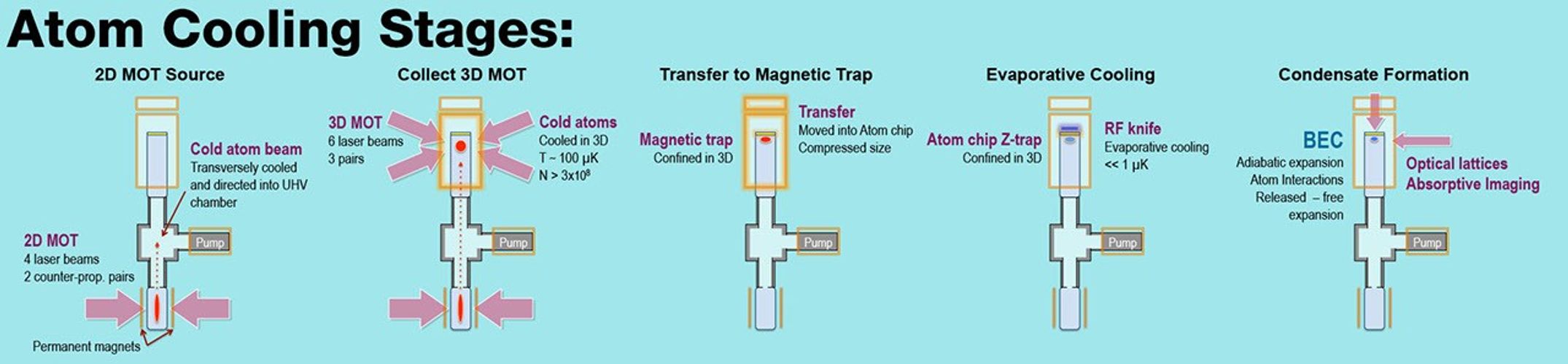
The process of laser cooling is summarized in the image below. The species of interest is exposed to a photon flux tuned to a particular resonance frequency. At resonance the photons impart momentum to the atoms. If the photon frequency is Doppler red-shifted from resonance then only atoms coming towards the laser beams will be affected. Those moving away from the laser will be unaffected by the photon flux. If laser beams are such that they are coming from all directions the atoms will be cooled from all directions. This laser cooling, lowers the atom population temperature to ~100 microKelvin, still above the condensate temperature.
The Instrument

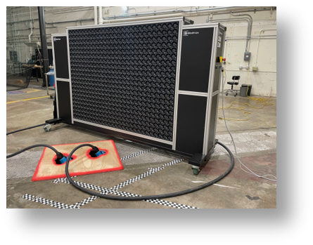
The Cold Atom Lab instrument utilizes commercial off the shelf (COTS) hardware and software to enable a rapid development. In the image above the Cold Atom Lab is shown in its quad lock configuration. On the left are the electronics components, which are cooled with liquid heat exchangers to maintain a safe operational temperature. On the right is the science module and laser assembly. Fiber-optic coupled lasers are used to simplify optic-mechanical design. Forced convection with fans is used to cool the lasers and science module. On the right is the science module, which is the heart of the Cold Atom Lab instrument. It is encased in a magnetic shield to attenuate the the magnetic field of the earth, which varies over the course of the orbit A more detailed image of the science module is shown in the lower figure. Note the 2D and 3D laser cooling stages, optical mounts, and structure.

Download the Cold Atom Lab Science Poster
Information for Researchers
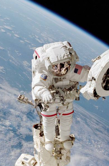
The Cold Atom Lab is a multi-user facility for the study of degenerate quantum gases in the microgravity environment of the International Space Station (ISS). The Cold Atom Lab is designed to be a simple but versatile experimental facility, capable of producing ultra-cold samples of several atomic species and loading them into very weak magnetic traps, or into a freefalling state, and studying them under a variety of conditions. The Cold Atom Lab is designed to be upgradable to meet the needs of specific future investigations.
An initial NASA Research Announcement (NRA) was released on July 13 (http://coldatomlab.jpl.nasa.gov/news/FunPhysicsResearch/) to solicit investigations related to the Cold Atom Lab. The selections were made in 2014 for the first set of flight investigators.
Overview of the Instrument
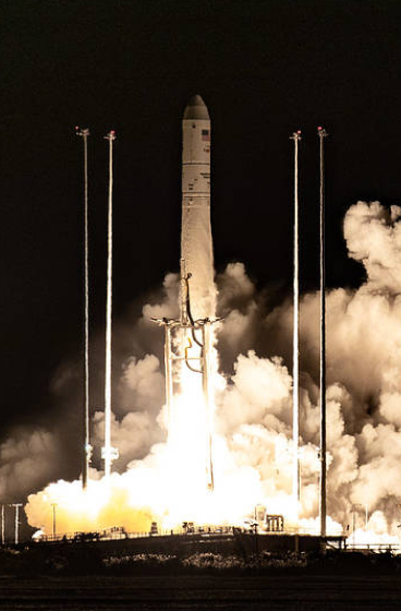
The Cold Atom Laboratory will be a compact, atom-chip based apparatus, capable of trapping both Rubidium (87Rb) and Potassium (either 39K or 41K), and of producing degenerate gases of each species, or of mixtures of Rb and either of the K isotopes, after a few seconds of collection and cooling. The atom chip approach is chosen because of power and volume constraints, though for many applications investigators may transfer the atoms into either a weak trap away from the chip, or into an optical trap. The Cold Atom Lab launched to the ISS onboard the Cygnus OA9 rocket in May 2018, in a foam-lined soft stowage cargo bag. After it was successfully delivered to the station, astronauts installed it in an EXPRESS rack inside the U.S. Destiny module, a pressurized "shirt-sleeves" laboratory aboard the ISS. The Cold Atom Lab takes up the entire top half of one EXPRESS rack. However, after install, no further astronaut involvement is necessary on a daily basis. The instrument is operated remotely from the ground via sequence control. Test sequences are developed by the Cold Atom Lab operations team in conjunction with Principal Investigators (P.I.'s). The phase one mission duration will last up to 36 months dedicated to flight P.I. led research. An extended mission of up to five years is expected, with upgrades to the facility possible.
A summary of the Cold Atom Laboratory mission objectives:
- The Cold Atom Lab will be a multi-user facility for the study ultra-cold quantum gases in the microgravity environment of the International Space Station
- The Cold Atom Lab will study Rb87, K39 and K41, and interactions between mixtures of Rb and either of the K isotopes;
- The Cold Atom Lab will study delta-kick cooling techniques to produce samples with residual kinetic energy below 100 pK and free expansion times greater than five seconds
- The Cold Atom Lab will study the properties of 87Rb, 39K, and 41K quantum gases loaded into optical lattices, in the presence of external magnetic fields tuned near interspecies and single species Feshbach resonances.
Additional features of the Cold Atom Lab system include the ability to image samples at high resolution through a window in the optical chip; with separate, wide field-of-view imaging also available. In each case standard absorption imaging will be utilized. Preparations of samples of atoms in arbitrary mixtures of internal states are facilitated by adiabatic rapid passage and microwave hyperfine state control. Table 1 gives the preliminary specifications of the facility.
Table 1. Preliminary performance specifications of the Cold Atom Lab facility
| 87Rb Condensate number | >20000 |
| 41K Condensate number | >5000 |
| 39K Condensate Number | >5000 at a phase space density one half of that needed for Bose-Einstein Condensation |
| Condensate Lifetime | >2 Seconds |
| Bragg Beam / Atom Interferometer | 0.6 mm diameter at 785 nm |
| Magnetic Field Bias | Variable up to 90 G |
| Feshbach Fields | Switching >2 G in less than 1 ms |
| Imaging resolution through atom chip window | <3 micron |
| Imaging resolution for imaging expanded samples | <20 micron |
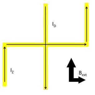
The Atom Chip
The Cold Atom Lab atom chip consists of lithographically patterned wires on a silicon substrate, which forms one wall of the Cold Atom Lab science chamber. Currents passing through these wires, in conjunction with external bias fields, allow for the formation of magnetic traps in a variety of configurations. Condensation is typically achieved in a trap in a "dimple" configuration, consisting of a wire pattern in a "z" configuration, with an additional waveguide superimposed on top, as shown in the figure below. Trap frequencies can be adjusted from 50-10,000 Hz, with approximately a 6:1 ratio to radial to axial frequencies. Condensates are typically formed in a tight trap about 100 microns from the atom chip. By ramping down the bias field they can be transported away from the chip's surface into a weaker trap. In Earth's gravity it is possible to move atoms up to 400 microns from the chip's surface; in microgravity this can be extended to greater than 1.0 mm.