Due to the lapse in federal government funding, NASA is not updating this website.

Suggested Searches

Technical diagram of the Landsat-D solar array system showing the spacecraft's power generation components. The illustration displays a TDRS high gain antenna at the top, a two-axis gimbal system, the instrument module at center, and a large deployable solar array panel extending diagonally. Key components are labeled including the antenna jettison mechanism, solar array drive, upper and lower power hinges, synchronization cables, spring-loaded deployment hinges, power hinge, retention fittings, and solar array jettison mechanism.

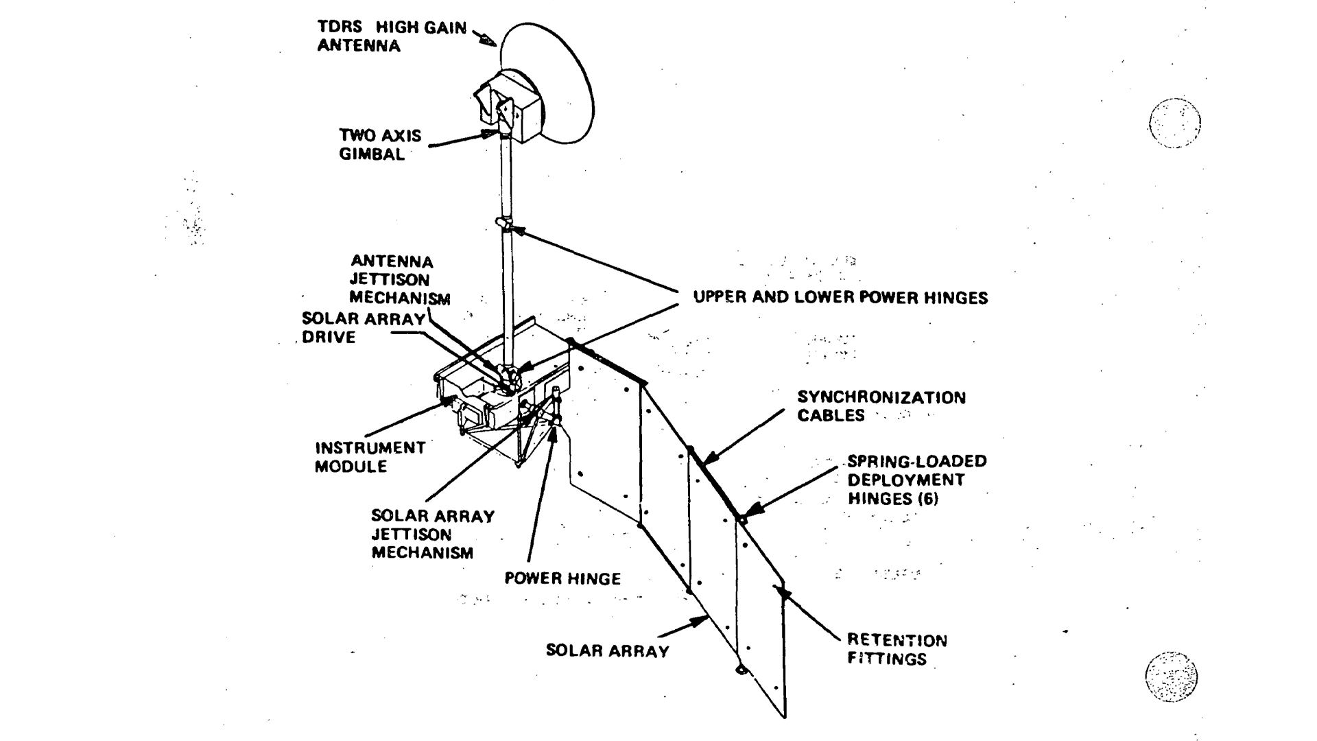
Landsat-D Solar Array Diagram

Technical schematic showing the Landsat-D solar array deployment system and power generation components, including the articulated solar panel, drive mechanisms, and communication antenna configuration.
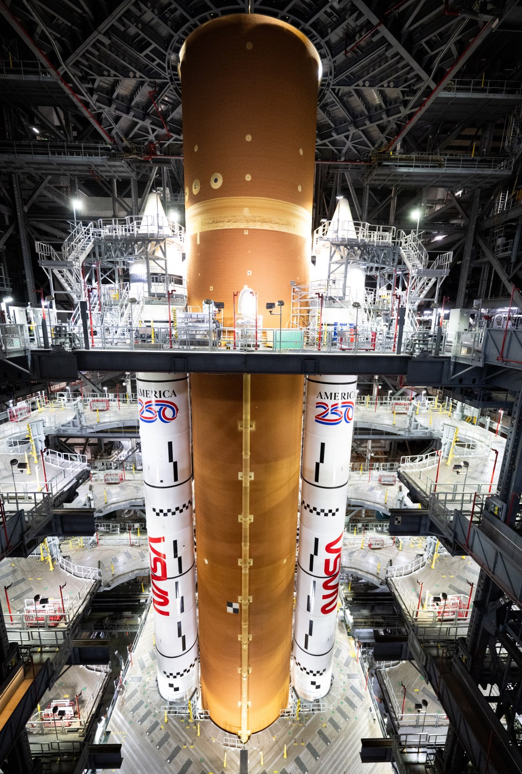
Image Credit: NASA
Download