


Communicating with Science Instruments
When astronauts return to the Hubble Space Telescope during Servicing Mission 4 (SM4), they will replace the Science Instrument Command and Data Handling, or SI C&DH, module. The SI C&DH provides all of the electronics to command Hubble's science instruments from the ground and to flow science and engineering data back to the ground.
Originally planned for an October 14, 2008 launch, the Space Shuttle Atlantis and her 22,000 pounds of Hubble cargo were in the final days of launch preparations, when the "A" side of the SI C&DH suffered a permanent electronic failure on September 27, 2008.
Because the SI C&DH is such a critical part of Hubble's science capability, the mission was postponed in order to allow engineers enough time to prepare the spare SI C&DH for inclusion into the servicing mission. Meanwhile, in order to restore science operations to the orbiting telescope, flight controllers on the ground successfully switched to the "B" side of the SI C&DH electronics and several additional spacecraft data system modules.
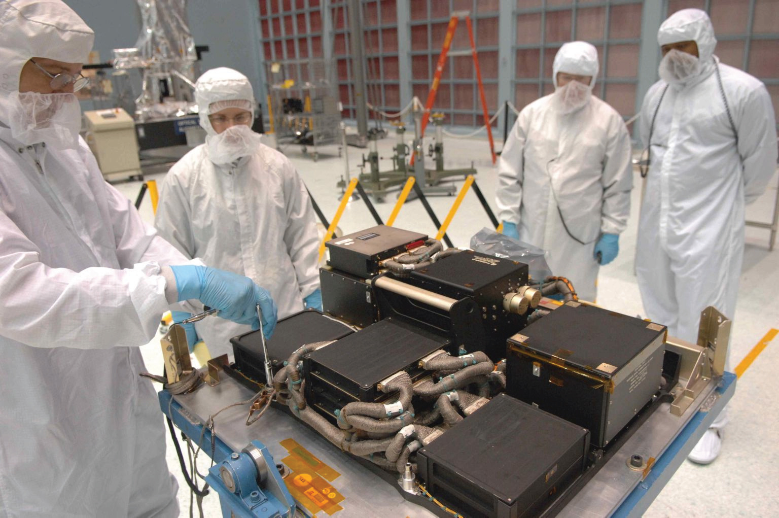
SI C&DH Components
The SI C&DH works with Hubble's data management Unit (DMU) to process, format, and temporarily store information on Hubble's digital recorders or transmit science and engineering data to the ground. The SI C&DH is a collection of fourteen components, arranged in six stacks that are mounted on a tray to create a single Orbital Replacement Unit (ORU). This tray is mounted to the inside of the System Support Module's Bay 10 door. These components work together to perform two basic functions: controlling Hubble's scientific instruments and formatting and storing the instruments' scientific and engineering data. There are 4 key-way bolts that position the tray onto the door and 6 captive bolts that secure the tray to the door. All 10 bolts have the Hubble "standard" 7/16-inch hex-head interface. There are no hand-mated electrical connectors on the SI C&DH tray. Instead, a bolt is turned to operate a "blind mate" interface that makes the electrical connections to the Hubble spacecraft. As far as ORUs go, the SI C&DH is relatively easy to get to and replace.
Capturing Science Data
The "brains" of the SI C&DH is the NASA Standard Spacecraft Computer, (NSSC-1). It contains a Central Processing Module (CPM) that runs the NSSC-1 software, four memory modules that store software and instrument commands and a Standard Interface (STINT) unit, which serves as the communications interface between the NSSC-1 and the Control Unit/Science Data Formatter, or CU/SDF. The flight software in the NSSC-1 computer monitors and controls the science instruments and the NICMOS Cooling System. The "heart" of the SI C&DH is the CU/SDF. It distributes all commands and data to designated destinations on the Hubble spacecraft such as the DMU, the NSSC-1, and the science instruments. It also translates the engineering and science data it receives into standard formats.
The remaining components of the SI C&DH perform basic housekeeping functions such as distributing and switching power and transmitting system signals. The SI C&DH components are configured as redundant sets, known as the "A" side and the "B" side. This redundancy allows for recovery from any one failure. A failure of the "A" side of the CU/SDF produced the SM4 delay. After the failure, ground controllers successfully switched the SI C&DH to the "B" side to recover science operations. NASA decided to replace the SI C&DH on SM4 in order to restore operational redundancy to Hubble.
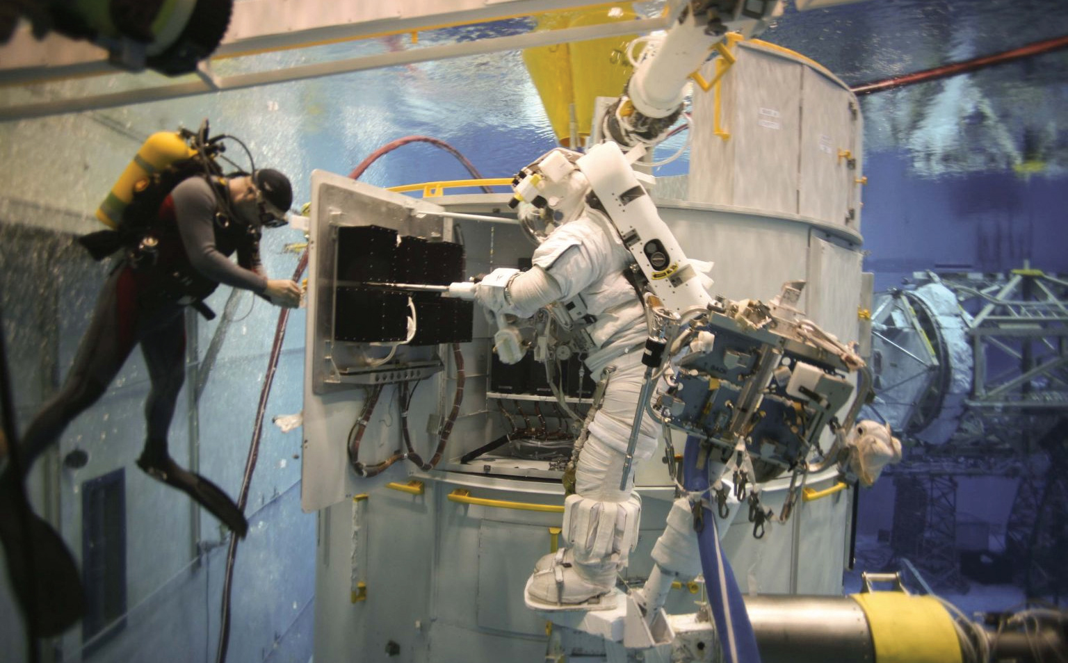
Replacing the SI C&DH
The replacement SI C&DH, designated SI C&DH-R, will ride to orbit on the Multi-Use Logistics Equipment Carrier (MULE). Spacewalking astronauts will replace the original SI C&DH by opening the spacecraft's Bay 10 door and loosening the 10 bolts that secure the SI C&DH to the door with a power tool. They will then break the eight-connector electrical interface to the spacecraft by turning a bolt. The old SI C&DH tray is removed from the door and the new unit is installed by reversing the procedure. After the astronauts complete these procedures, ground controllers will run a quick test to confirm that the box was properly installed. This will be followed by a full functional test of the new unit to verify that it is properly performing.