


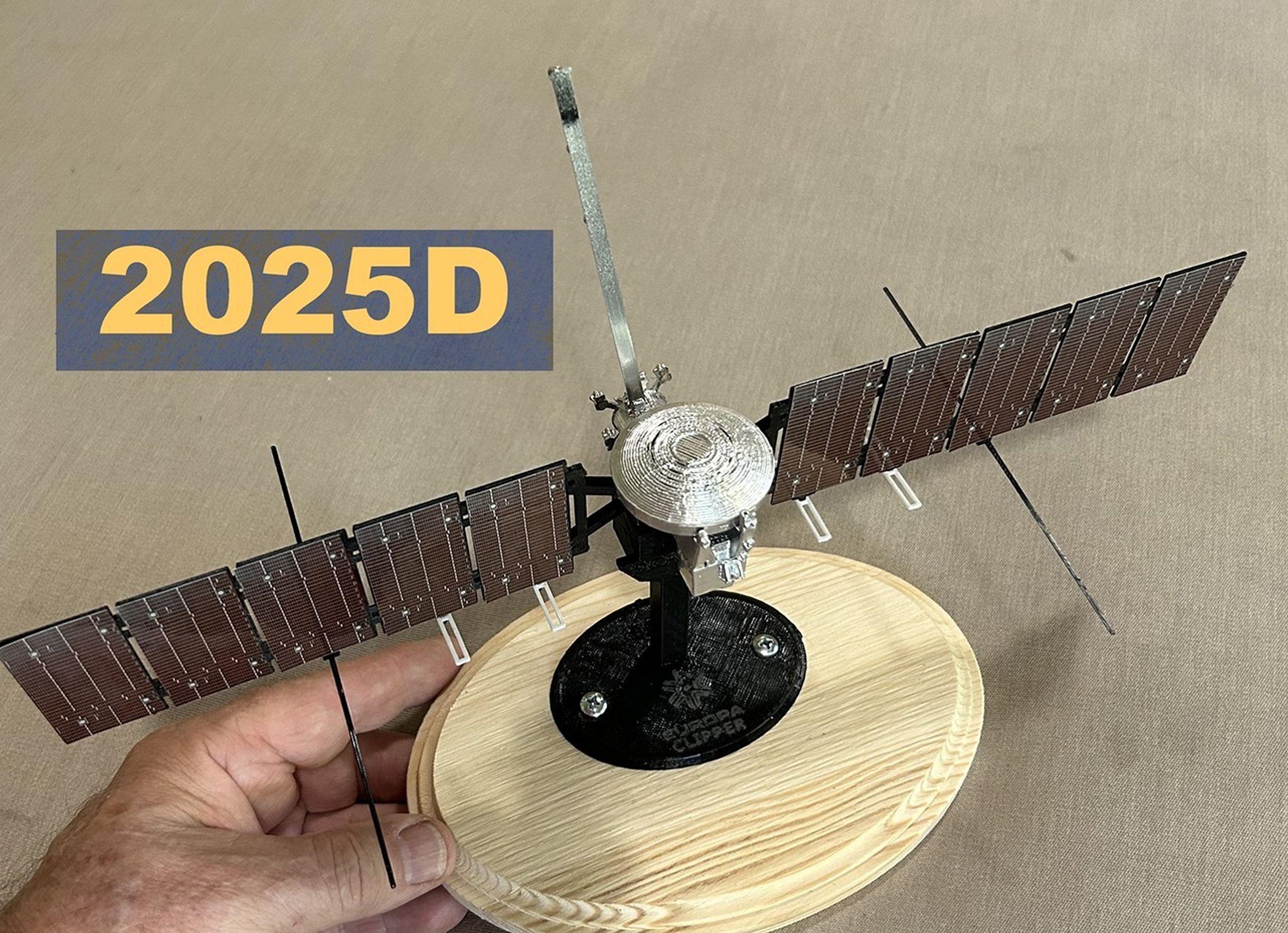
Europa Clipper 3D Model — Version 2025D
| Language |
|
|---|
(Updated from version 2022G) This is a model for anyone who might wish to see Europa Clipper's major components with all its science instruments, and manipulate the solar-array-radar wings. The model very roughly emulates the mechanical freedom of the solar array to rotate, which is less than 360 degrees.
The spacecraft's X, Y, and Z body axes are plainly marked on the model. “VSCA” marked on the model and its stand indicates the spacecraft's velocity vector (V) during Standard Closest Approach (SCA) at Europa.
The following engineering components are identifiable on the model:
- High-Gain Antenna
- HGA Radome Sun Shield
- Medium Gain Antenna
- Three Fan-Beam Antennas
- Three Low-Gain Antennas
- Plume Shield for ECM (effective prior to ECM deployment)
- Four Rocket-Engine Modules, each with six nozzles
- Four Reaction Wheels
- Two Stellar-Reference Units
- Two pairs of Sun Sensors
- Main Thermal Radiator
- Two Solar Array wings
- the Propulsion module, too, of course.
And the Science Instruments:
- ECM: three sensors on boom, Europa Clipper Magnetometer
- Four PIMS apertures, Plasma Instrument for Magnetic Sounding
- SUDA aperture, Surface Dust mass Analyzer
- MASPEX aperture, Mass Spectrometer for Planetary Exploration Europa
- Two apertures for EIS, Europa Imaging System: the Narrow-Angle Camera, and the smaller Wide-Angle Camera
- MISE aperture, Mapping ImagingSpectrometer for Europa, plus its adjacent thermal radiator
- Two UVS apertures, Ultraviolet Spectrograph for Europa
- E-THEMIS aperture, Europa Thermal Emission Imaging System
- Six REASON dipole antenna pairs on the wings, Radar for Europa Assessment and Sounding, Ocean-to Near surface; the long ones are HF antennas, and the shorter ones are VHF.
Not included (to enable easy printing and assembly) are the spacecraft's eight pairs of struts that supported the folded solar panels through launch and separation from the Falcon Heavy's upper stage. Note: on the spacecraft, there is no mechanical axle joining the Solar Arrays; that's just a model contrivance. To identify the instruments and spacecraft components, refer to the NASA website, and this rotating view of the spacecraft.
Printing: All the model's components are designed to be simple enough for standard “fused deposition modeling” (FDM) flat-bed printing, also known as “fused filament fabrication.” Users can carry the three .stl files to a desktop 3D printer's "slicing" software and use its default settings without any rafts or support material required.
Scale: If printed as-is with no size adjustment, the scale is approximately 1:106. While the scale is not exact, this version successfully reproduces key visual cues and technical details. Enlargements have been successfully printed up to 1:30 scale.
Solar Array Wings: Add some maroon-colored tape — or glue on the solar-cell images provided — to represent the photovoltaic solar cells. Snip off the REASON VHF antennas, remove their sprues, and press each one onto its connector on the panel edges, perpendicular to the panels (see images). Glue in place. Add the longer REASON HF antennas (see photos), one on each wing. If they stay in place without glue, it’s easy to print and replace broken ones if necessary later on. IMPORTANT: Use an emery board to smooth the +X Wing connector rod to ensure smooth rotation; then when inserting through the Body, observe "+X" markings on the Wing and on the Bodyand orient them as shown in the picture (to ensure proper engagement of the mechanical stop). Snap to join the two wings through the spacecraft body. Then apply thin glue to the joint, while supporting the model in a way that will not let glue drip into the rotating sleeve.
Version 2025D: This model includes features and refinements that make it easier to assemble than previous versions. For example, the Solar Array Wings snap together and align much better. Also, the Solar Array now incorporates a mechanical stop. Positioning of the minus-Z PIMS instrument is corrected. To contend with the constraints of FDM printing, a new "+Z Panel" has been added, better representing the Stellar Reference Units, and the SUDA and MASPEX instruments. (Previously the SRU print-supports could easily be confused with the apertures). Finally, this version collects all the parts into three files: the Body, the Wings, and the Stand.
This Europa Clipper Scale Model is dedicated to the memory of Hirai Isao, the master of accurate spacecraft scale modeling. Hirai-san operated the Scale Model Company in Hawthorne, California from 1967 until his passing in 2024.
Print Settings
How to Print
The individual part .stl files available here are designed for successful printing on a common desktop FDM printer like those often used at home, at school, or in the local library.
The user guide for each kind of 3D printer will likely specify a preferred utility program to prepare the .stl files (for example slicing and writing g-code, or proprietary code, to a removable medium). That utility's default settings are probably appropriate for printing these model parts. Be sure "Support Structures" and "Raft" settings are set to "Off." These simple files can print well with no support material added.
Color information is not encoded into any of these files.
Custom Section


License
Europa Clipper Scale Model (version 2025D) is licensed under the Creative Commons — Public Domain Dedication license. More information on the model is available at https://www.thingiverse.com/thing:4903128.
See a smaller, far simpler, and more robust version, Tiny Clipper, at https://www.thingiverse.com/thing:5995293.