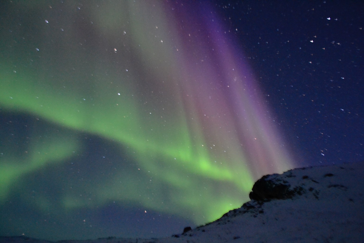
The energetic electrons that drive the aurora borealis (the northern lights) have a rich and very dynamic structure that we currently do not fully understand. Much of what we know about these electrons comes from instruments that have fundamental limitations in their ability to sample multiple energies with high time resolution. To overcome these limitations, NASA is using an innovative approach to develop instrumentation that will enhance our measurement capabilities by more than an order of magnitude—revealing a wealth of new information about the amazing physics happening within the aurora.
Typical electron instruments rely on a technique called electrostatic deflection, which requires changing a voltage to select different energies of electrons to measure. These instruments have been flown on many different space missions and have provided almost all of the in-situ electron measurements made inside the aurora. They work great when observing on timescales of seconds or even down to around a tenth of a second, but they fundamentally cannot observe down to smaller (millisecond) timescales due to the time it takes to sweep through voltages.
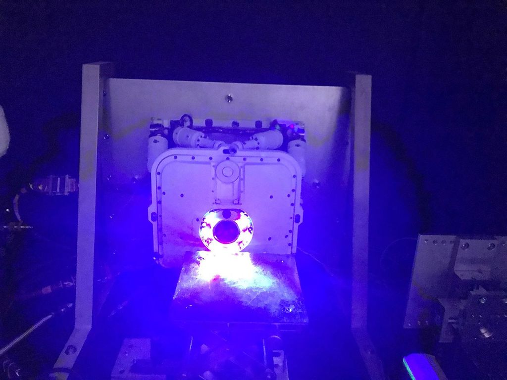
Ground-based optical observations of the aurora have shown that there can be rapid spatial and temporal variations that are beyond the observing capabilities of traditional electron instruments. Therefore, members of the Geophysics Laboratory at NASA’s Goddard Space Flight Center developed an instrument called the Acute Precipitating Electron Spectrometer (APES) that can measure electron precipitation within the aurora at a one millisecond cadence. APES uses a strong magnetic field inside the instrument to separate electrons with different energies onto different spatial regions of the detector. This method allows the instrument to measure the entire electron energy spectrum simultaneously at a very high rate (every 1 ms).
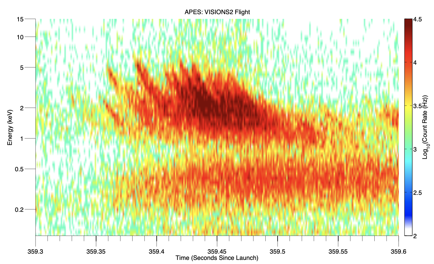
In the design of APES, one major trade-off had to be made. For the magnetic field geometry to work properly, the instrument can only observe in one direction. This concept works well if the goal is just to measure the precipitating (downgoing) electrons in the aurora that ultimately hit the atmosphere. However, we know that electrons in the aurora also move in other directions; in fact, these electrons contain a lot of information about other physical processes happening farther out in space.
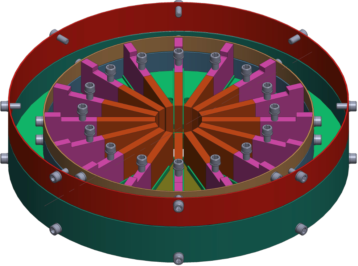
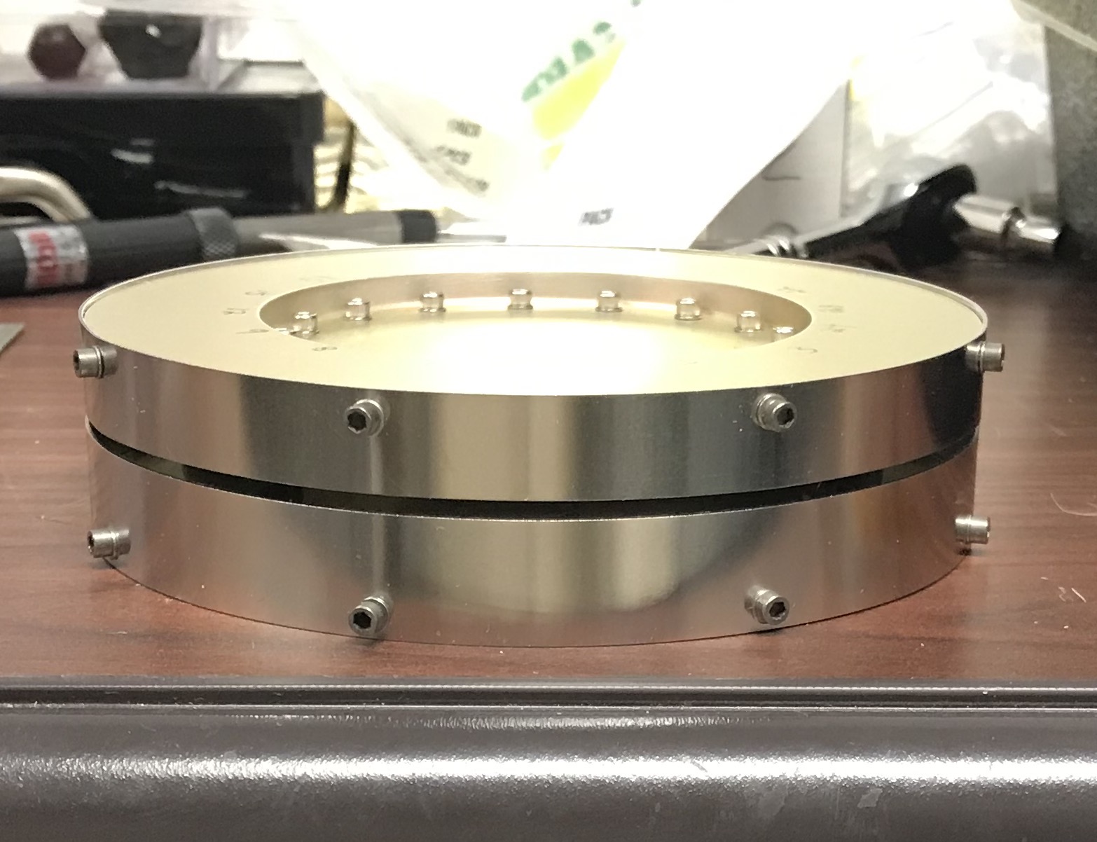
To enable measurement of electrons in more than one direction, the Goddard team developed the APES-360 instrument concept. To create the APES-360 design, the team employed the same operating principles used in APES, but updated them to accommodate a multi-look direction geometry that covers a 360-degree field of view using 16 different sectors. The team had to overcome several technical challenges to develop the APES-360 concept. In particular, the electronics design had to accommodate many more anodes (charge detecting surfaces) and the associated circuitry in a small area.
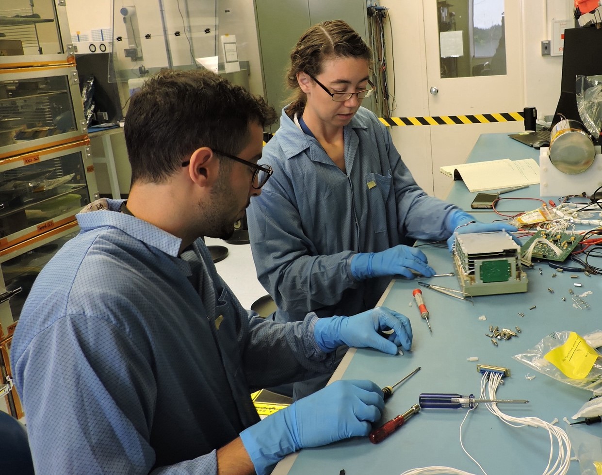
The APES-360 prototype that is currently being built will be tested and calibrated at Goddard and will fly on a sounding rocket into active aurora in the winter of 2025. This flight will provide real-life data from inside the aurora that will be used to validate the instrument performance and inform future design improvements.
The APES-360 instrument is being designed to fit into a CubeSat form factor so that it can be used on future CubeSat missions to study the aurora. The instrument could also ultimately be flown on larger orbital missions, as well.
PROJECT LEAD:
Dr. Robert G Michell, NASA Goddard Space Flight Center (GSFC)
SPONSORING ORGANIZATIONS:
Heliophysics, Geospace Physics Laboratory (GSFC Code 673) and H-TIDeS.

