


![This schematic appears in the ERTS Reference Manual that was prepared by General Electric prior to the Landsat 1 (ERTS-1) launch in 1972. The schematic shows the Landsat 1 flight profile, from liftoff (0) to spacecraft separation (10). The manual tells us, “an all-inertial guidance system, consisting of an inertial sensor package and guidance computer, controls the vehicle and sequence of operations from liftoff to spacecraft separation. The flight profile is presented in [this figure] .”](https://assets.science.nasa.gov/dynamicimage/assets/science/missions/landsat/2020/07/launch.jpg?w=1152&h=1152&fit=clip&crop=faces%2Cfocalpoint)
ERTS Flight Profile
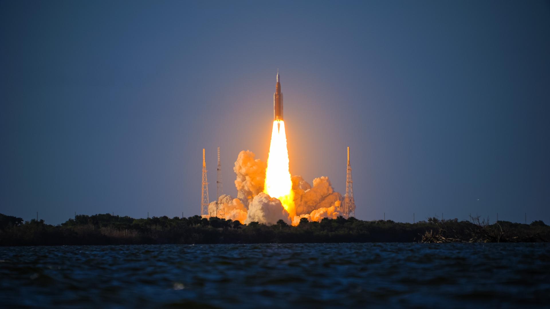
This schematic appears in the ERTS Reference Manual that was prepared by General Electric prior to the Landsat 1 (ERTS-1) launch in 1972. The schematic shows the Landsat 1 flight profile, from liftoff (0) to spacecraft separation (10). The manual tells us, “an all-inertial guidance system, consisting of an inertial sensor package and guidance computer, controls the vehicle and sequence of operations from liftoff to spacecraft separation. The flight profile is presented in [this figure] .”
Image Credit: Earth Resources Technology Satellite Reference Manual
- X
https://science.nasa.gov/image-detail/amf-1f19c1d5-71a1-4792-83a5-d0ee5cf80a50/
Image CreditEarth Resources Technology Satellite Reference Manual
Size1152x1152px
![This schematic appears in the ERTS Reference Manual that was prepared by General Electric prior to the Landsat 1 (ERTS-1) launch in 1972. The schematic shows the Landsat 1 flight profile, from liftoff (0) to spacecraft separation (10). The manual tells us, “an all-inertial guidance system, consisting of an inertial sensor package and guidance computer, controls the vehicle and sequence of operations from liftoff to spacecraft separation. The flight profile is presented in [this figure] .”](https://assets.science.nasa.gov/dynamicimage/assets/science/missions/landsat/2020/07/launch.jpg)