Chapter 11: Onboard Systems
Page One | Page Two | Page Three | Page Four
Electrical Power Supply and Distribution Subsystems
On today's interplanetary spacecraft, roughly between 300 W and 2.5 kW of electrical power is required to supply all the computers, radio transmitters and receivers, motors, valves, data storage devices, instruments, hosts of sensors, and other devices.
Cassini used roughly 1 kW. A power supply for an interplanetary spacecraft must provide a large percentage of its rated power over a lifetime measured in years or decades.
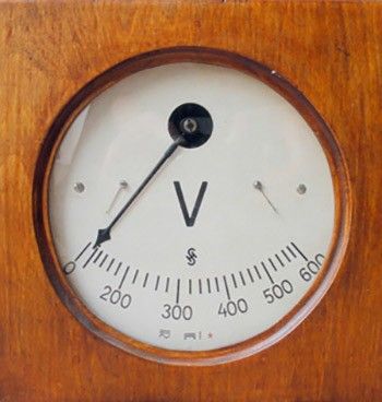
Here is a quick primer on voltage, current, power, AC and DC.
How does a spacecraft meet its demanding electrical power needs? Choices of technology to meet these requirements are today constrained largely to two: photovoltaics (PV) and radioisotope power systems (RPS). The latter includes radioisotope thermoelectric generators (RTGs) such as those currently powering Voyager, and that powered Cassini.
Primary battery power is an option for use only on short-lived missions such as the Galileo or Huygens atmospheric-entry probes.
Photovoltaics
As the term suggests, photovoltaic materials have the ability to convert light directly to electricity. An energy conversion efficiency of about 29 percent was achieved in July 2000, and gains of a few more percent may be possible over the next decades.
Crystalline silicon and gallium arsenide are typical choices of materials for deep-space applications. Gallium arsenide crystals are grown especially for photovoltaic use, but silicon crystals are available in less-expensive standard ingots which are produced mainly for consumption in the microelectronics industry.
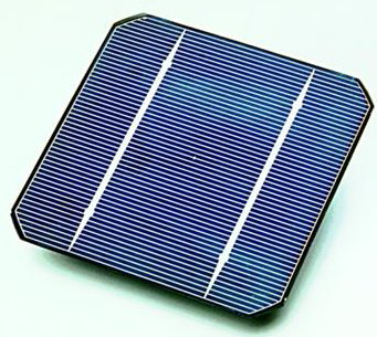
When exposed to direct sunlight at 1 au, a current of about one Ampere at 0.25 volt can be produced by a 6 cm diameter crystalline silicon solar cell. Gallium arsenide is notably tougher and more efficient. Amorphous silicon, less expensive and less efficient than crystalline, is employed in ultra-thin layers for residential and commercial PV applications.
To manufacture spacecraft-grade solar cells, crystalline ingots are grown and then sliced into wafer-thin discs, and metallic conductors are deposited onto each surface: typically a thin grid on the sun-facing side and a flat sheet on the other. Spacecraft solar panels are constructed of these cells trimmed into appropriate shapes and cemented onto a substrate, sometimes with protective glass covers. Electrical connections are made in series-parallel to determine total output voltage. The resulting assemblies are called solar panels, PV panels, or solar arrays. The cement and the substrate must be thermally conductive, because in flight the cells absorb infrared energy and can reach high temperatures, though they are more efficient when kept to lower temperatures.
Farther than about the orbit of Mars, the weaker sunlight available to power a spacecraft would require panels larger than practicable because of the increased launch mass and the difficulty in supporting, deploying, and articulating them.
Magellan and Mars Observer were designed to use solar power, as was Deep Space 1, Mars Global Surveyor, Mars Pathfinder, and Lunar Prospector. Topex/Poseidon, the Hubble Space Telescope, and most other Earth-orbiters use solar power.
Solar panels typically have to be articulated to remain at optimum Sun point, though they may be off-pointed slightly for periods when it may be desirable to generate less power. Spinning spacecraft may have solar cells on all sides that can face the Sun (see Lunar Prospector). Prolonged exposure to sunlight causes photovoltaics' performance to degrade in the neighborhood of a percent or two per year, and more rapidly when exposed to particle radiation from solar flares.
In addition to generating electrical power, solar arrays have also been used to generate atmospheric drag for aerobraking operations. Magellan did this at Venus, as did MGS at Mars. Gold-colored aerobraking panels at the ends of MGS's solar arrays, visible in the image above, added to the aerodynamic drag for more efficient aerobraking.
Radioisotope Power Systems
Radioisotope power systems (RPS) enable, or significantly enhance, missions to destinations where inadequate sunlight, harsh environmental conditions, or operational requirements make other electrical power systems unfeasible.
RPS offer the key advantage of operating continuously, independent of unavoidable variations in sunlight. Such systems can provide power for long periods of time and at vast distances from the Sun. Additionally, they have little sensitivity to temperature, radiation or other space environmental effects. They are ideally suited for missions involving autonomous, long duration operations in the most extreme environments in space and on planetary surfaces.
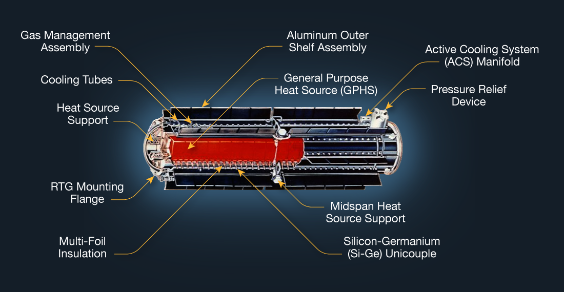
RPS, as currently designed for space missions, contain an isotopic mixture of the radioactive element plutonium in the form of an oxide, pressed into a ceramic pellet. The primary constituent of these fuel pellets is the plutonium isotope 238 (Pu238). The pellets are arranged in a converter housing where they function as a heat source due to the natural decay of the plutonium. RTGs convert the heat into electricity through the use of simple thermocouples, which make use of the Seebeck effect and have no moving parts.
Since they remain thermally hot, RPS present advantages and disadvantages. Cassini employed much of its Radioisotope Thermoelectric Generators' (RTGs) radiant heat inside its thermal blanketing, to warm the spacecraft and propellant tanks.
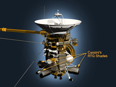
On the other hand, RTGs must be located on the spacecraft in such a way to minimize their impact on infrared detecting science instruments. Galileo's RTGs were mounted behind shades to hide the near-infrared mapping spectrometer from their radiant heat. Shades were used on Cassini for similar reasons.
Seven generations of RPSs have been flown in space by the United States since 1961, powering 26 missions that have enabled world-renowned scientific exploration of the Moon, the Sun, Venus, Mars, Jupiter, Saturn, Uranus, Neptune, and Pluto.
All of the RPSs on these historic solar system exploration missions have worked beyond their design lifetimes. An eighth RPS configuration, called the Multi-Mission Radioisotope Thermoelectric Generator (MMRTG), is now in use on the Mars Science Laboratory rover, Curiosity.
Any NASA mission that proposes to use an RPS has to undergo a comprehensive multi-agency environmental review, including public meetings and open comment periods during the mission planning and decision-making process, as part of NASA's compliance with the National Environmental Policy Act (NEPA). Additionally, any such mission proposed by NASA would not launch until formal approval for the mission's nuclear launch safety is received from the Office of the President.
Electrical Power Distribution
Virtually every electrical or electronic component on a spacecraft may be switched on or off via command. This is accomplished using solid-state or mechanical relays that connect or disconnect the component from the common distribution circuit, called a main bus. On some spacecraft, it is necessary to power off some set of components before switching others on in order to keep the electrical load within the limits of the supply. Voltages are measured and telemetered from the main bus and a few other points in the electrical system, and currents are measured and telemetered for many individual spacecraft components and instruments to show their consumption.
Typically, a shunt-type regulator maintains a constant voltage from the power source. The voltage applied as input to the shunt regulator is generally variable but higher than the spacecraft's required constant bus voltage. The shunt regulator converts excess electrical energy into heat, most of which is radiated away into space via a radiating plate. On spacecraft equipped with articulating solar panels, it is sometimes possible, and desirable for reasons of spacecraft thermal control, to off-point the panels from the Sun to reduce the regulator input voltage and thus reduce the amount of heat generated by the regulator.
Electrical Power Storage
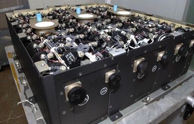
Spacecraft which use photovoltaics usually are equipped with rechargeable batteries that receive a charge from the main bus when the solar panels are in the sunlight, and discharge into the bus to maintain its voltage whenever the solar panels are shadowed by the planet or off-pointed during spacecraft maneuvers. Nickel-cadmium (Ni-Cad) batteries are frequently used. After hundreds of charge-discharge cycles, this type of battery degrades in performance, but may be rejuvenated by carefully controlled deep discharge and recharge, an activity called reconditioning.

