Chapter 4: Trajectories
Chapter Objectives
Upon completion of this chapter you will be able to describe the use of Hohmann transfer orbits in general terms and how spacecraft use them for interplanetary travel. You will be able to describe the general concept of exchanging angular momentum between planets and spacecraft to achieve gravity assist trajectories.
When traveling among the planets, it's a good idea to minimize the propellant mass needed by your spacecraft and its launch vehicle. That way, such a flight is possible with current launch capabilities, and costs will not be prohibitive.
The amount of propellant needed depends largely on what route you choose. Trajectories that by their nature need a minimum of propellant are therefore of great interest.
Hohmann Transfer Orbits
To launch a spacecraft from Earth to an outer planet such as Mars using the least propellant possible, first consider that the spacecraft is already in solar orbit as it sits on the launch pad. This existing solar orbit must be adjusted to cause it to take the spacecraft to Mars: The desired orbit's perihelion (closest approach to the Sun) will be at the distance of Earth's orbit, and the aphelion (farthest distance from the Sun) will be at the distance of Mars' orbit. This is called a Hohmann Transfer orbit. The portion of the solar orbit that takes the spacecraft from Earth to Mars is called its trajectory.
From the previous chapter, we know that the task is to increase the apoapsis (aphelion) of the spacecraft's present solar orbit. Recall from Chapter 3...
A spacecraft's apoapsis altitude can be raised by increasing the spacecraft's energy at periapsis.
Well, the spacecraft is already at periapsis. So the spacecraft lifts off the launch pad, rises above Earth's atmosphere, and uses its rocket to accelerate in the direction of Earth's revolution around the Sun to the extent that the energy added here at periapsis (perihelion) will cause its new orbit to have an aphelion equal to Mars' orbit. The acceleration is tangential to the existing orbit. How much energy to add? See the Rocket & Space Technology website.
After this brief acceleration away from Earth, the spacecraft has achieved its new orbit, and it simply coasts the rest of the way. The launch phase is covered further in Chapter 14.
Earth to Mars via Least Energy Orbit
Getting to the planet Mars, rather than just to its orbit, requires that the spacecraft be inserted into its interplanetary trajectory at the correct time so it will arrive at the Martian orbit when Mars will be there. This task might be compared to throwing a dart at a moving target. You have to lead the aim point by just the right amount to hit the target. The opportunity to launch a spacecraft on a minimum-energy transfer orbit to Mars occurs about every 25 months.
To be captured into a Martian orbit, the spacecraft must then decelerate relative to Mars using an orbit insertion rocket burn or some other means. To land on Mars from orbit, as did Viking, the spacecraft must decelerate even further using a rocket burn to the extent that the lowest point of its Martian orbit will intercept the surface of Mars. Since Mars has an atmosphere, final deceleration may also be performed by aerodynamic braking direct from the interplanetary trajectory, and/or a parachute, and/or further retrograde burns.
Inward Bound
To launch a spacecraft from Earth to an inner planet such as Venus using least propellant, its existing solar orbit (as it sits on the launch pad) must be adjusted so that it will take it to Venus. In other words, the spacecraft's aphelion is already the distance of Earth's orbit, and the perihelion will be on the orbit of Venus.
This time, the task is to decrease the periapsis (perihelion) of the spacecraft's present solar orbit. Recall from Chapter 3...
A spacecraft's periapsis altitude can be lowered by decreasing the spacecraft's energy at apoapsis.
To achieve this, the spacecraft lifts off of the launch pad, rises above Earth's atmosphere, and uses its rocket to accelerate opposite the direction of Earth's revolution around the Sun, thereby decreasing its orbital energy while here at apoapsis (aphelion) to the extent that its new orbit will have a perihelion equal to the distance of Venus's orbit. Once again, the acceleration is tangential to the existing orbit.
Of course the spacecraft will continue going in the same direction as Earth orbits the Sun, but a little slower now. To get to Venus, rather than just to its orbit, again requires that the spacecraft be inserted into its interplanetary trajectory at the correct time so it will arrive at the Venusian orbit when Venus is there. Venus launch opportunities occur about every 19 months.
Type I and II Trajectories
If the interplanetary trajectory carries the spacecraft less than 180 degrees around the sun, it's called a Type-I Trajectory. If the trajectory carries it 180 degrees or more around the Sun, it's called a Type-II.
Gravity Assist Trajectories
Chapter 1 pointed out that the planets retain most of the solar system's angular momentum. This momentum can be tapped to accelerate spacecraft on so-called "gravity-assist" trajectories. It is commonly stated in the news media that spacecraft such as Voyager, Galileo, and Cassini use a planet's gravity during a flyby to slingshot it farther into space. How does this work? By using gravity to tap into the planet's tremendous angular momentum.
In a gravity-assist trajectory, angular momentum is transferred from the orbiting planet to a spacecraft approaching from behind the planet in its progress about the sun.
Experimenters and educators may be interested in the Gravity Assist Mechanical Simulator, a device you can build and operate to gain an intuitive understanding of how gravity assist trajectories work. The linked pages include an illustrated "primer" on gravity assist.
Consider Voyager 2, which toured the Jovian planets. The spacecraft was launched on a Type-II Hohmann transfer orbit to Jupiter. Had Jupiter not been there at the time of the spacecraft's arrival, the spacecraft would have fallen back toward the sun, and would have remained in elliptical orbit as long as no other forces acted upon it. Perihelion would have been at 1 au, and aphelion at Jupiter's distance of about 5 au.
However, Voyager's arrival at Jupiter was carefully timed so that it would pass behind Jupiter in its orbit around the Sun. As the spacecraft came into Jupiter's gravitational influence, it fell toward Jupiter, increasing its speed toward maximum at closest approach to Jupiter. Since all masses in the universe attract each other, Jupiter sped up the spacecraft substantially, and the spacecraft tugged on Jupiter, causing the massive planet to actually lose some of its orbital energy.
The spacecraft passed on by Jupiter since Voyager's velocity was greater than Jupiter's escape velocity, and of course it slowed down again relative to Jupiter as it climbed out of the huge gravitational field. The speed component of its Jupiter-relative velocity outbound dropped to the same as that on its inbound leg.
But relative to the Sun, it never slowed all the way to its initial Jupiter approach speed. It left the Jovian environment carrying additional orbital angular momentum stolen from Jupiter. Jupiter's gravity served to connect the spacecraft with the planet's ample reserve of angular momentum. This technique was repeated at Saturn and Uranus.
Voyager 2 Gravity Assist Velocity Changes
The same can be said of a baseball's acceleration when hit by a bat: angular momentum is transferred from the bat to the slower-moving ball. The bat is slowed down in its "orbit" about the batter, accelerating the ball greatly. The bat connects to the ball not with the force of gravity from behind as was the case with a spacecraft, but with direct mechanical force (electrical force, on the molecular scale, if you prefer) at the front of the bat in its travel about the batter, translating angular momentum from the bat into a high velocity for the ball.
(Of course in the analogy a planet has an attractive force and the bat has a repulsive force, thus Voyager must approach Jupiter from a direction opposite Jupiter's trajectory and the ball approaches the bat from the direction of the bats trajectory.)
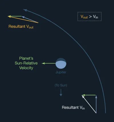
See the vector diagram showing the spacecraft's speed relative to Jupiter during a gravity-assist flyby. The spacecraft slows to the same velocity going away that it had coming in, relative to Jupiter, although its direction has changed. Note also the temporary increase in speed nearing closest approach.
When the same situation is viewed as Sun-relative in the diagram below, we see that Jupiter's Sun-relative orbital velocity is added to the spacecraft's velocity, and the spacecraft does not lose this component on its way out. Instead, the planet itself loses the energy.
The massive planet's loss is too small to be measured, but the tiny spacecraft's gain can be very great. Imagine a gnat flying into the path of a speeding freight train.
Gravity assists can be also used to decelerate a spacecraft, by flying in front of a body in its orbit, donating some of the spacecraft's angular momentum to the body. When the Galileo spacecraft arrived at Jupiter, passing close in front of Jupiter's moon Io in its orbit, Galileo lost energy in relation to Jupiter, helping it achieve Jupiter orbit insertion, reducing the propellant needed for orbit insertion by 90 kg.
The gravity assist technique was championed by Michael Minovitch in the early 1960s, while he was a UCLA graduate student working during the summers at JPL. Prior to the adoption of the gravity assist technique, it was believed that travel to the outer solar system would only be possible by developing extremely powerful launch vehicles using nuclear reactors to create tremendous thrust, and basically flying larger and larger Hohmann transfers.
An interesting fact to consider is that even though a spacecraft may double its speed as the result of a gravity assist, it feels no acceleration at all. If you were aboard Voyager 2 when it more than doubled its speed with gravity assists in the outer solar system, you would feel only a continuous sense of falling. No acceleration. This is due to the balanced tradeoff of angular momentum brokered by the planet's -- and the spacecraft's -- gravitation.
Enter the Ion Engine
All of the above discussion of interplanetary trajectories is based on the use of today's system of chemical rockets, in which a launch vehicle provides nearly all of the spacecraft's propulsive energy. A few times a year the spacecraft may fire short bursts from its chemical rocket thrusters for small adjustments in trajectory. Otherwise, the spacecraft is in free-fall, coasting all the way to its destination. Gravity assists may also provide short periods wherein the spacecraft's trajectory undergoes a change.
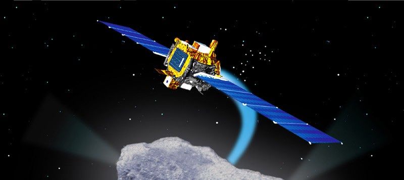
But ion electric propulsion, as demonstrated in interplanetary flight by Deep Space 1 -- and employed on the Dawn science mission to the asteroids -- works differently. Instead of short bursts of relatively powerful thrust, electric propulsion uses a more gentle thrust continuously over periods of months or even years. It offers a gain in efficiency of an order of magnitude over chemical propulsion for those missions of long enough duration to use the technology. Ion engines are discussed further under Propulsion in Chapter 11.
Click the image below for more information about Deep Space 1. The Japan Aerospace Exploration Agency's asteroid explorer HAYABUSA also employed an ion engine.
Even ion-electric propelled spacecraft need to launch using chemical rockets, but because of their efficiency they can be less massive, and require less powerful (and less expensive) launch vehicles. Initially, then, the trajectory of an ion-propelled craft may look like the Hohmann transfer orbit. But over long periods of continuously operating an electric engine, the trajectory will no longer be a purely ballistic arc.

