


RBV
The Return Beam Vidicon Camera System (RBV) was carried by the first three Landsat satellites and used high-resolution television cameras to capture Earth imagery in multiple spectral bands.
Overview
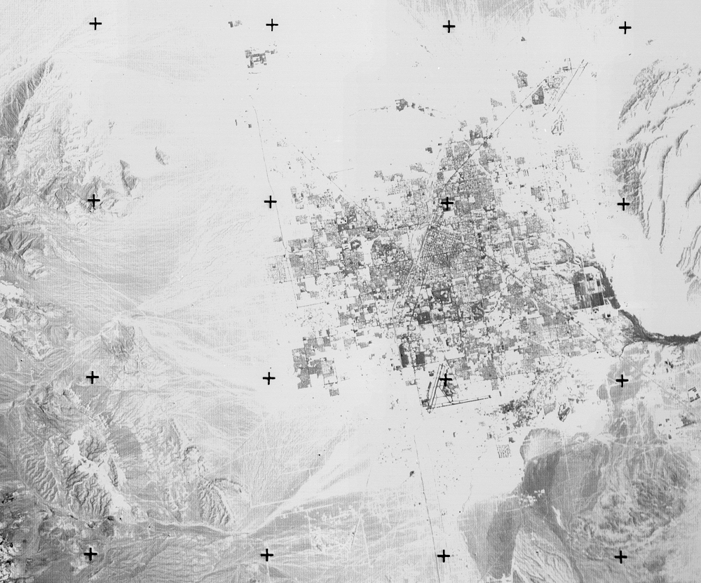
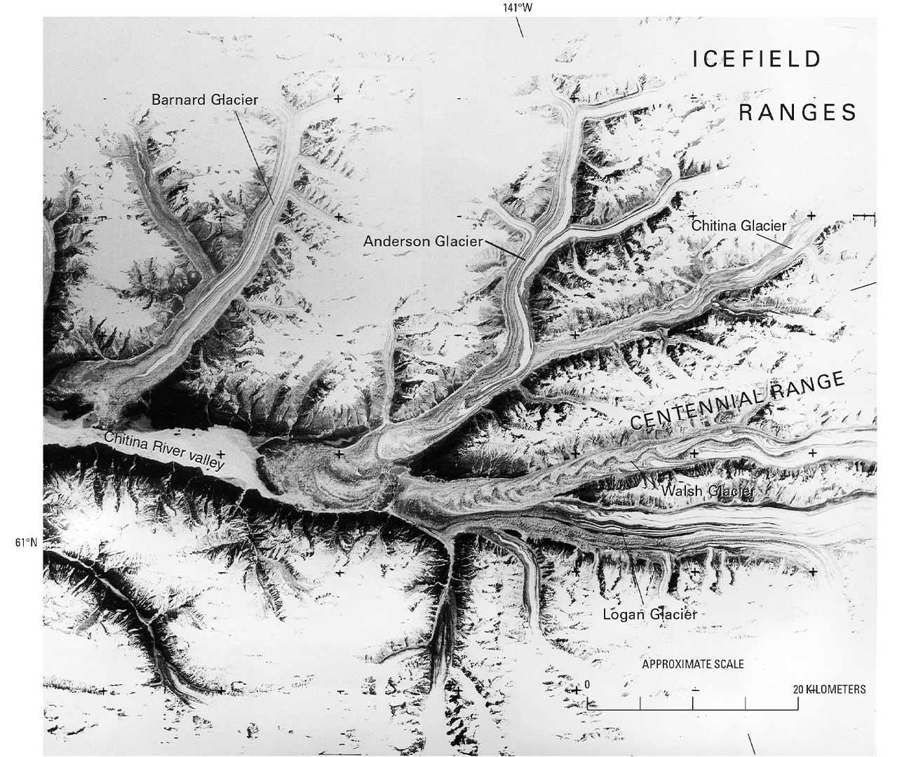
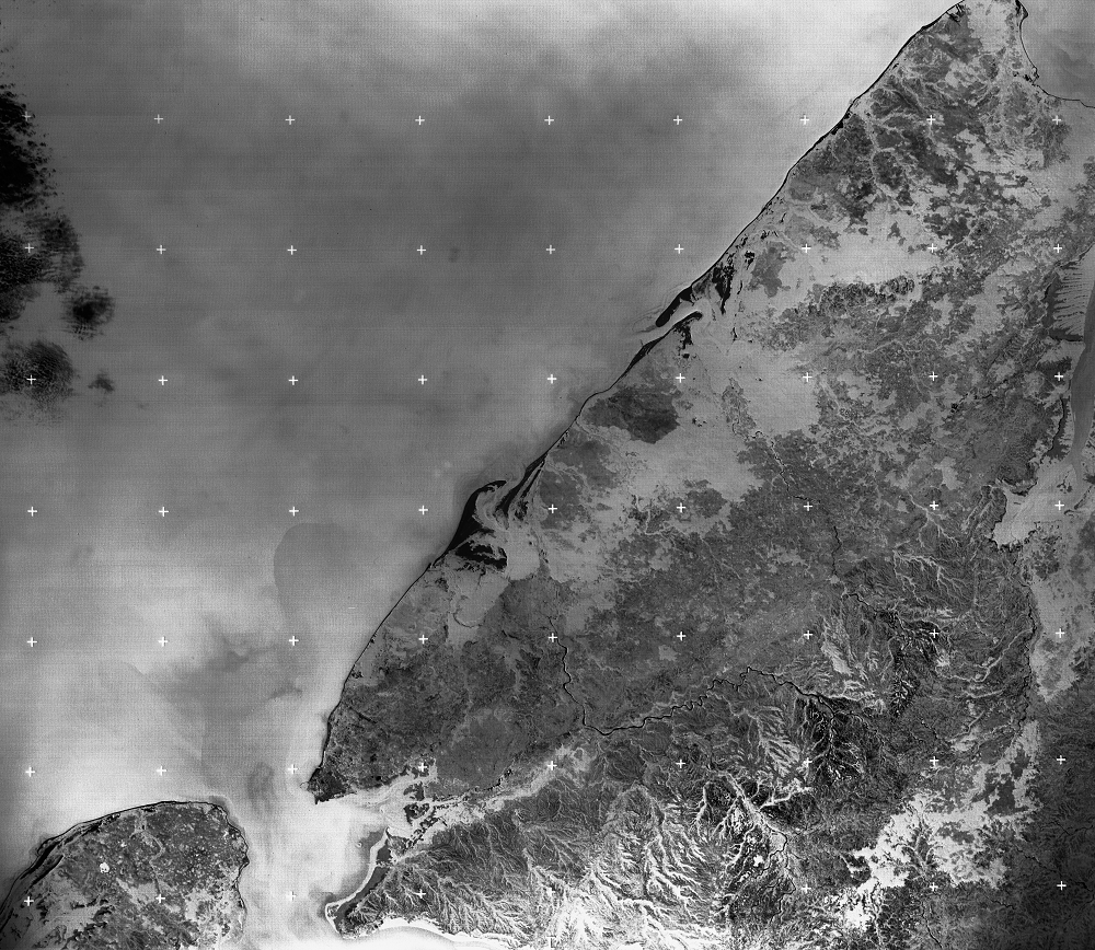
The Return Beam Vidicon (RBV) was a television camera system with a much higher spatial resolution (3,300 lines by 3,300 samples) than traditional analog television (640 lines by 500 samples). The three cameras (on Landsats 1 and 2 RBV) and two cameras (on Landsat 3 RBV) viewed the same 185-square-kilometer (115-square-mile) area in three different spectral bands in the green, red, and near-infrared portion of the spectrum.
While designed primarily to observe Earth’s land surface, the RBV camera system also conducted meteorological studies, including monitoring snow cover, monsoon clouds, and weather systems. The RBV was originally intended to be Landsat 1’s primary sensor; however, a power outage shortly after launch ended the RBV’s operational life. RBV instruments were included on Landsats 2 and 3, but the Multispectral Scanner System (MSS) became the primary instrument of the early Landsat missions.

Requirements
Requirements for the RBV instrument included:
- view the same 185 by 185 kilometers (115 by 115 miles) square area as the MSS instrument in three different spectral bands in the green, red and near-infrared portion of the spectrum.
- provide instrument resolution necessary to obtain a spatial resolution of 80 meters from a spacecraft orbiting the Earth from an altitude of 917 kilometers once every 103.34 minutes.

Design
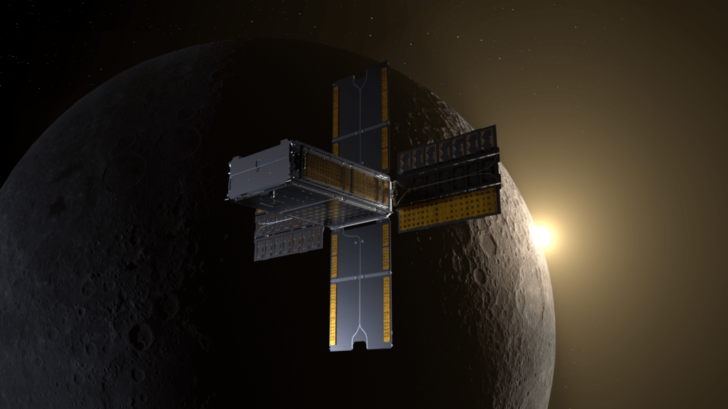
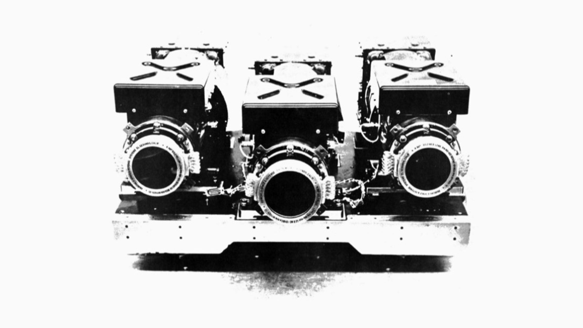
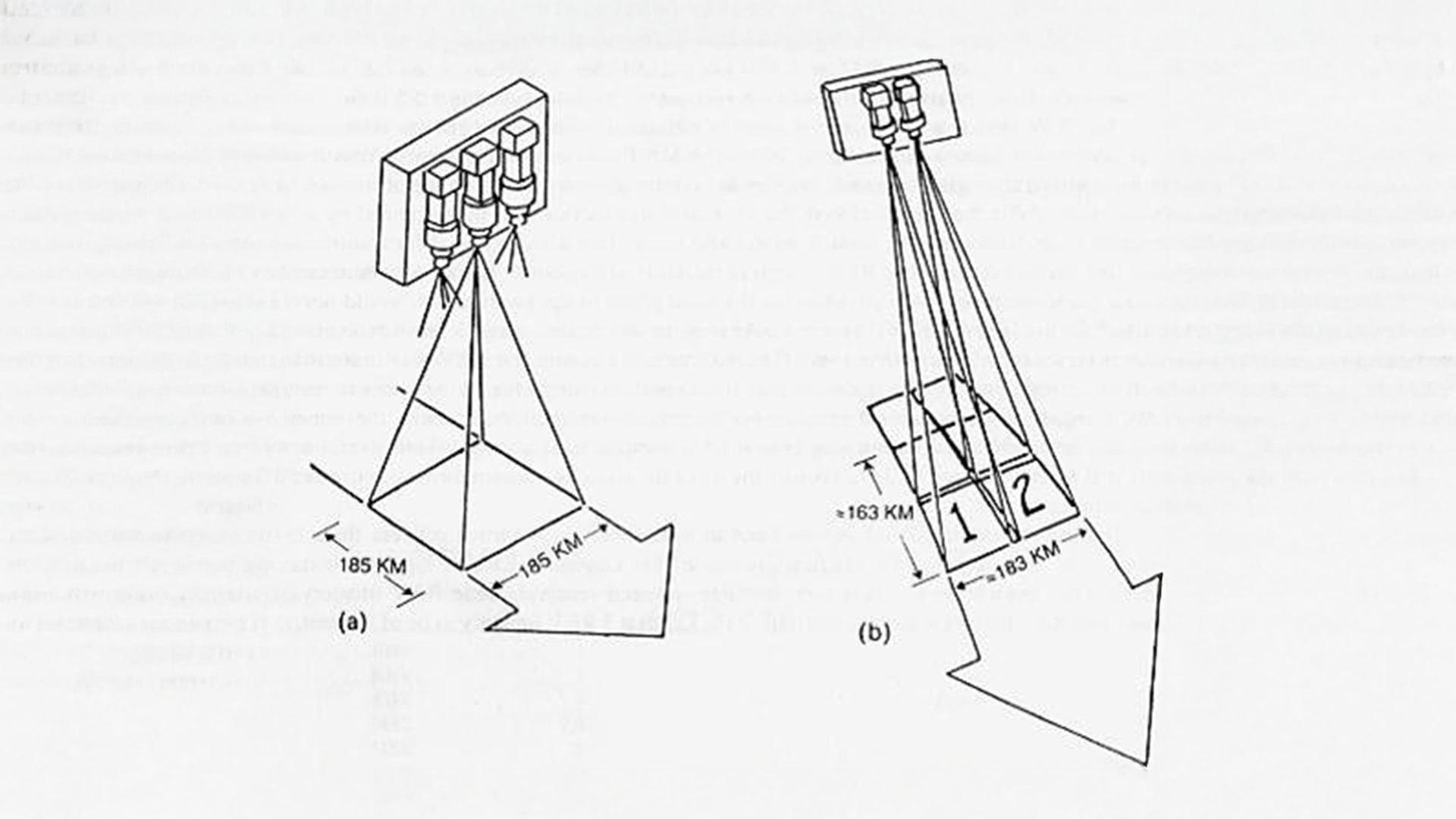
Landsats 1 and 2 carried a Return Beam Vidicon (RBV) camera system with three independent cameras simultaneously viewing the identical scene in three spectral bands.
Each camera on the Return Beam Vidicon (RBV) contained an optical lens, a sensor, a thermoelectric cooler, deflection and focus coils, a mechanical shutter, erase lamps, and sensor electronics. The cameras were similar except for the spectral filters contained in the lens assemblies that provided separate spectral viewing regions.
When the camera’s shutter opened, incoming light would hit a sensitive surface inside the camera tube and create an image. Then an electron beam would “read” the image line by line, processing it into a digital signal (data) that could be transmitted down to Earth in real-time or stored onboard using the wideband video tape recorder.
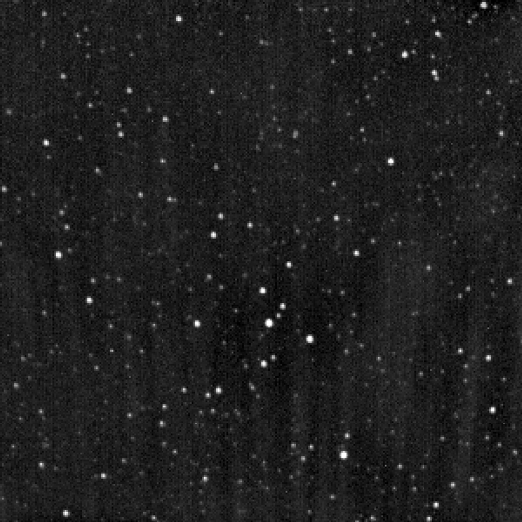
The resulting images were gray scale. The amount of white represented the intensity of energy measured in each of the three spectral bands. The images were mapped to red, green, and blue (primary colors of light) to create a full-color image - similar to how a tv or computer monitor works.
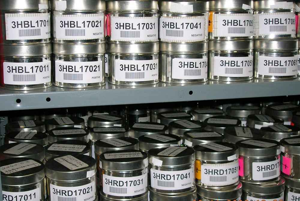
RBV imagery was processed from the wideband video tape to 70mm film until September 1980, when digital production started. New analog-to-digital preprocessing corrected the data both radiometrically and geometrically, then stored it onto high-density digital tapes (HDTs) at NASA Goddard Space Flight Center (GSFC). The data was then transmitted via satellite to USGS’s EROS Data Center. Data was made available as digital products (computer compatible tapes) and photographic prints at a scale of 1:500,000.

Enhancements on Landsat 3
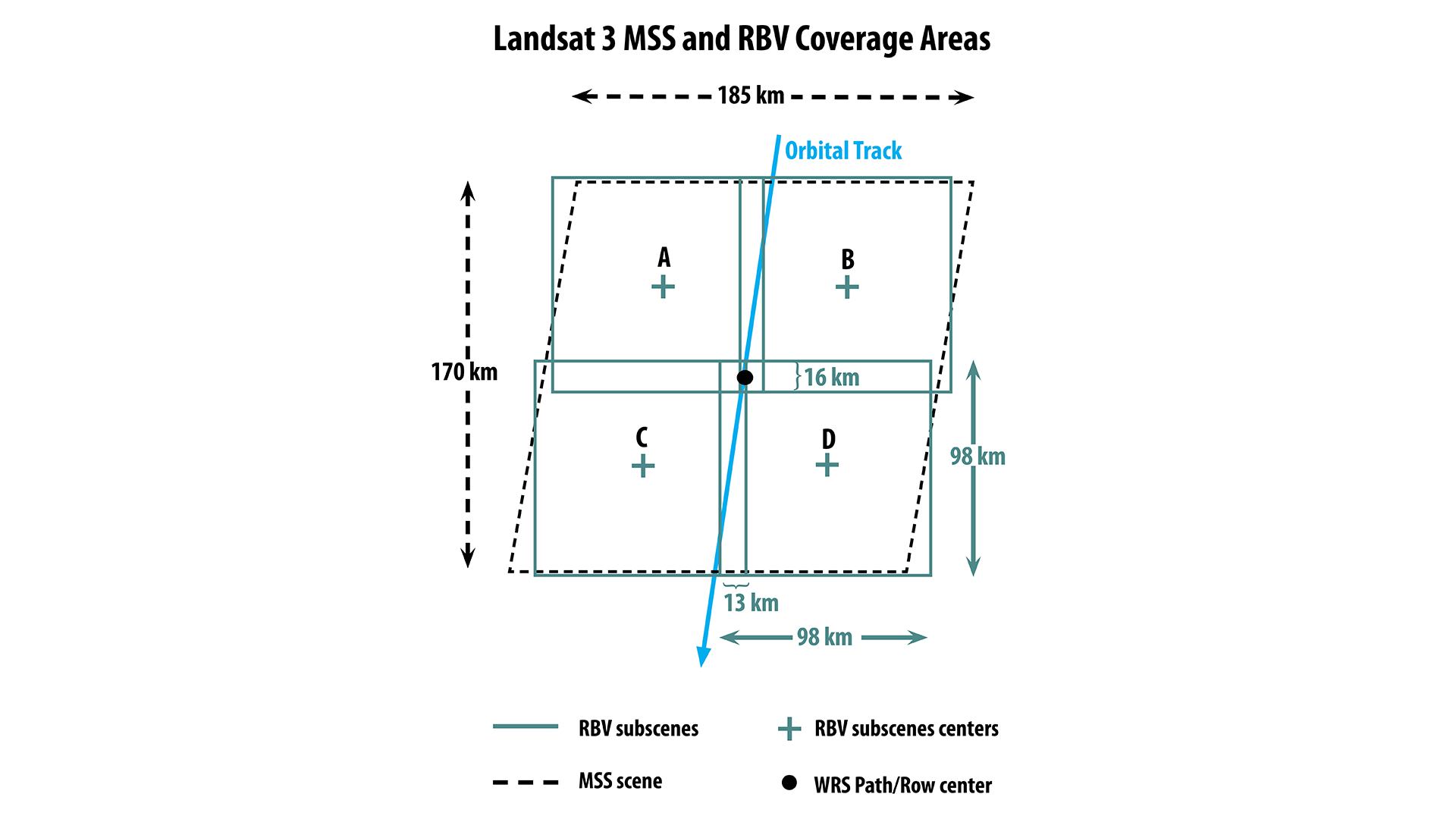
The Landsat 3 RBV system utilized just two vidicon cameras, both of which sense data in a single broad panchromatic band from 0.53 to 0.75 µm with at a higher spatial resolution than earlier RBV instruments on Landsats 1 and 2. It also had a different configuration where the two cameras were shuttered alternately, twice each, in the same time it takes for one MSS scene to be acquired. This shuttering sequence results in four RBV "subscenes" for every MSS scene acquired, similar to the four quadrants of a square.
Spectral Bands
| Band # (L1-L2) | Band # (L3) | Wavelength (µm) | Resolution* |
|---|---|---|---|
| 1 | N/A | 0.475–0.575 | 80 m |
| 2 | N/A | 0.58–0.68 | 80 m |
| 3 | N/A | 0.69-0.83 | 80 m |
| N/A | 1 | 0.53-0.75 | 40 m |
Data: 3.5 MHz FM video
Landsat 3’s RBV collected data in a single broad panchromatic band from 0.53 to 0.75 µm with a 40 m resolution.
History
Shortly after launch, Landsat 1 experienced an unexpected power surge that shorted the power supply of one of the two tape recorders. Three days later, the RBV’s power-switching circuit caused a second massive power surge that physically rocked the satellite, turning the satellite and lowering its orbit. The failure left the instrument in a perpetual “on” state.
Because this incident nearly resulted in the loss of the satellite, NASA’s Associate Administrator Charles Mathews immediately ordered that the RBV never be reactivated. This effectively ended the instrument's operational life on Landsat 1 after just 15 days after only acquiring 1,400 scenes.
While an alternate relay sequence could have restored RBV control, NASA chose permanent shutdown due to the complex workaround procedures, limited tape recorder capacity, and the MSS instrument's unexpectedly superior performance. The MSS proved to have greater photometric accuracy and a valuable near-infrared band unavailable on the RBV.
Ironically, this failure proved fortuitous—the MSS's exceptional image quality and digital capabilities so exceeded expectations that it became the mission's primary success story, establishing the technological foundation for all future Earth observation satellites and transforming what was initially considered an "experimental" backup instrument into the gold standard for space-based remote sensing.