PROJECT
Sub-arcsecond X-ray telescope optics and high-resolution, high-efficiency X-ray transmission grating spectrometers
SNAPSHOT
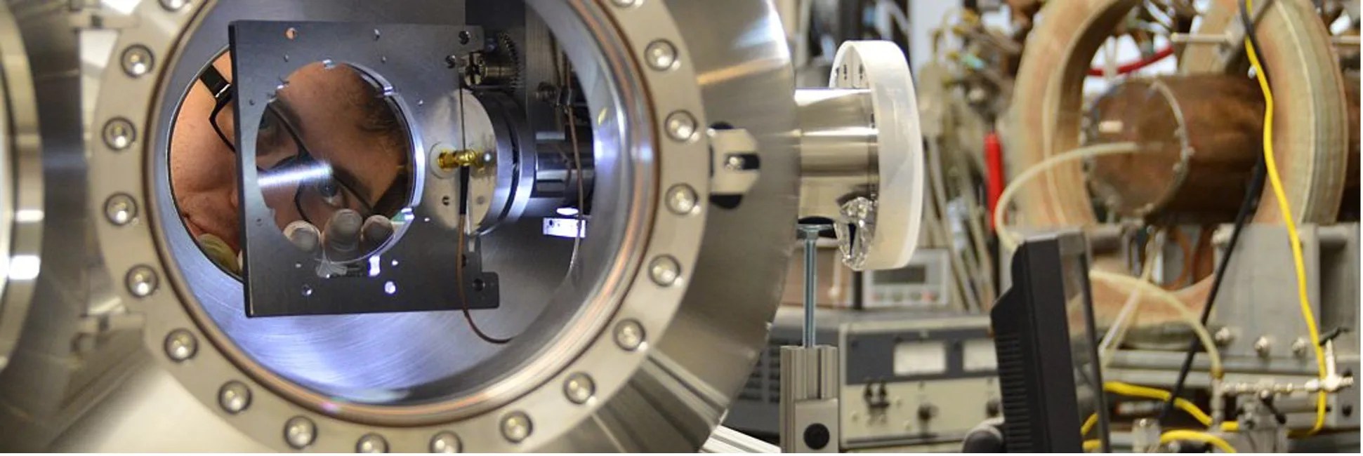
A NASA-sponsored team at the MIT Space Nanotechnology Lab is developing high-performance space instrumentation for more powerful future X-ray telescopes that will study the dynamics of the high-energy universe.
In the 50 years since the launch of Uhuru, the first X-ray astronomy satellite, our knowledge about the high-energy universe has exploded. Measurements of celestial X-ray emission and absorption have taught us about supermassive black holes, neutron stars, accretion disks, and many more phenomena in the high-temperature universe. Naturally, many new questions have arisen that cannot be answered with old technology. Today, NASA’s great X-ray observatory Chandra has lasted over two decades in space, and the Agency is considering potential future strategic mission concepts with vastly improved performance such as Lynx. This improved performance relies on cutting-edge technology, such as ultra-precise X-ray mirrors and high-performance X-ray diffraction gratings. These mirrors and gratings are tens to hundreds of millimeters in size and sub-millimeter thin, but must be fabricated, shaped, and assembled with nanometer precision.
X-rays are highly energetic electromagnetic radiation, mostly known for their ability to penetrate soft organic tissue for the imaging of bones or teeth. In our universe, X-rays are generated by highly energetic processes, usually associated with temperatures in the range of millions to tens of millions of degrees. Examples of X-ray-generating environments include the coronas of stars, accretion disks in binary systems, and active galactic nuclei. In addition, gases and plasmas between these sources and Earth can absorb some of these X-rays, so X-ray observations also teach us about the dynamic interstellar and intergalactic material. Astronomers need to image X-ray sources with high angular resolution and break down the X-ray light into its finest spectral components to understand the conditions and abundance of elements at the source and the processes that generate the X-rays. A NASA-sponsored team at the Kavli Institute’s Space Nanotechnology Lab (SNL) at the Massachusetts Institute of Technology (MIT) is working to develop advanced mirrors and gratings that will enable future X-ray telescopes.
More Precise Mirrors
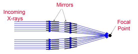
Building an X-ray telescope is challenging, mostly due to the way X-rays interact with matter. In astronomy most of the X-rays of interest are less energetic (“softer”) than medical X-rays and are more easily absorbed by matter. In addition, the index of refraction for X-rays is very close to one for most materials, which means that lenses can barely bend X-rays. Both of these reasons make it impractical to build traditional telescope lenses for imaging or prisms for spectral analysis of celestial X-ray sources. Instead, in a method akin to skipping rocks on a pond, scientists use mirrors to reflect the X-rays at very shallow angles (below the so-called critical angle) toward a focal point (see figure below). It can take hundreds of nested shells of mirrors to densely fill the aperture of a large telescope. The mirrors must be as thin as possible to avoid wasting the precious collecting area and to keep mass low. Each mirror must have a precisely bent shape and must be precisely aligned with respect to all the other mirrors. For a future mission concept such as Lynx, the requirement for the telescope angular resolution is half an arcsecond. For best reflectivity the mirrors must be coated with very thin, nanometer-thick films, typically made of metals. However, metal films are inherently stressed and can deform the thin mirrors by several micrometers, which is beyond acceptable tolerances. In addition, the amount and distribution of stress in the film is often difficult to predict or control.
A team at the Kavli Institute’s SNL has explored ways to correct for mirror bending from coating stress by imparting a counter-balanced stress on the mirror's back side in three different ways: ion implantation, lithographic patterning of thermal oxide, and laser micromachining. Each method calls for measuring the mirror shape before and after coating and calculating the coating’s stress distribution from the measured deformation. Then a correction stress map is calculated for the mirror’s back side that would bend the mirror back into its original shape. Next a 2D correction or “dose” map is generated that will lead to the desired correction stress distribution, and the correction is applied to the mirror’s back side using one of the three methods, as discussed below.
The ion implantation method shoots high-energy ions into the mirror’s back side, creating a stressed layer a few micrometers below the surface that bends the mirror back into shape. The thermal oxide patterning method first grows a thermal oxide film – which has a very well-defined stress exceeding the metal film stress – on the back of a silicon mirror, bending the mirror in the opposite direction. Then a specially designed 2D honeycomb pattern with varying wall thicknesses is etched into the thermal oxide, removing just enough stressed material to compensate for the metal film stress. The laser micromachining method also uses an overcompensating thermal oxide film on the back of the mirror, but with this method the excess oxide is removed in a designed pattern by femtosecond laser pulses (lasers whose pulses are less than a trillionth of a second long).
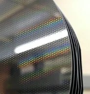
A key problem common to all three approaches is the accurate measurement of the shape of the mirrors: they are so thin that they sag under their own weight, and the forces required to hold them in place can easily deform them by many times the nano-scale tolerances. The near-cylindrical shape of the mirrors provides additional measurement and processing challenges. So far, the thermal oxide patterning method has shown the most success, demonstrating shape improvement of Lynx-prototype, iridium-coated, silicon mirrors fabricated by a team at Goddard Space Flight Center (GSFC) by a factor of five, and reducing the effect of film stress to the level of about 0.5 arc-second slope error (root-mean-squared).
The team continues to improve these methods and extend them to correct arbitrary deformations.
High-performance Gratings
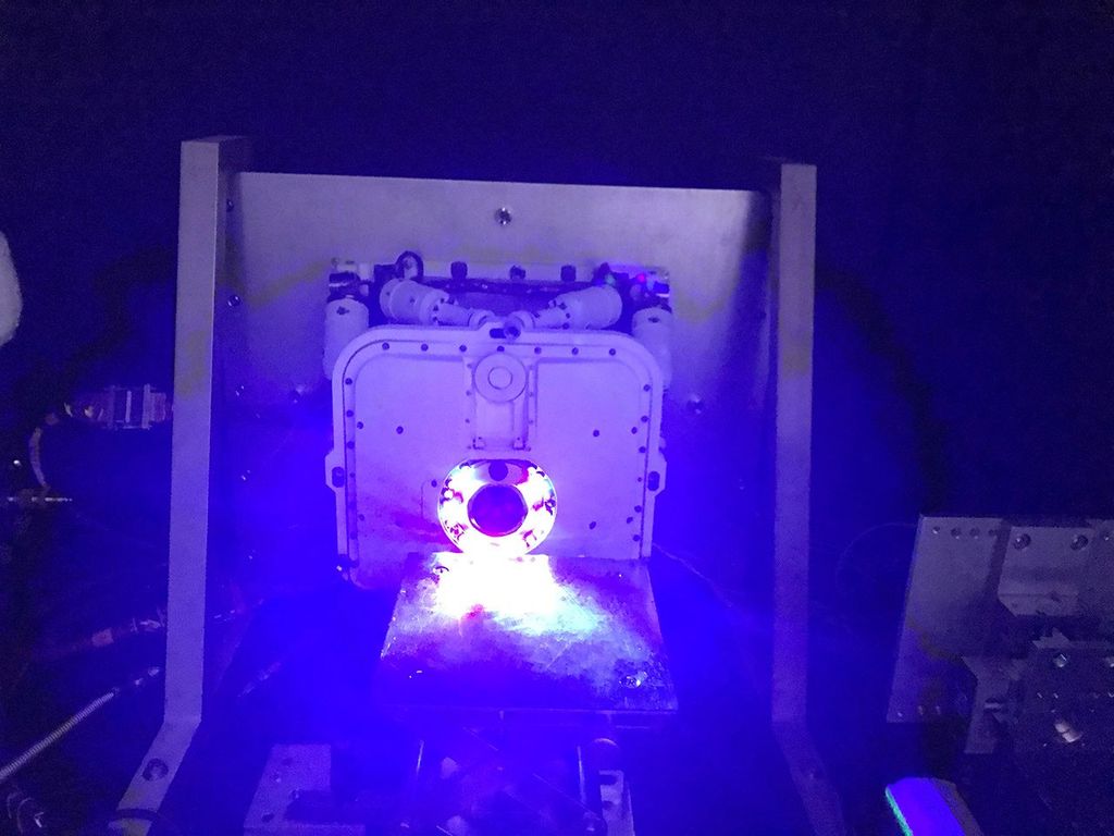
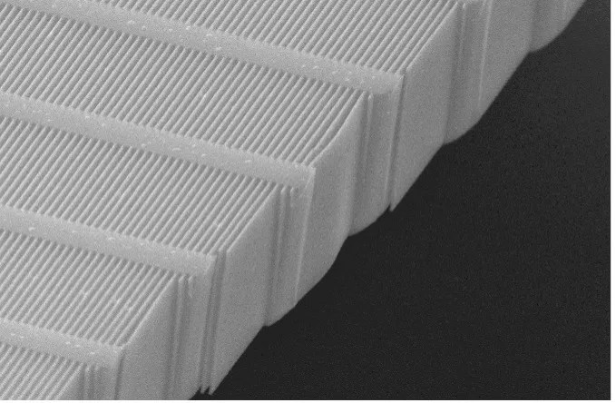
Mirrors cannot separate X-rays according to their energy or wavelength. For the softest X-rays of astrophysical interest, separation is best accomplished using a diffraction grating spectrometer, which splits the X-rays into different diffraction orders, separated by angle according to their wavelengths, such that they can be detected by a CCD camera. The MIT team has recently developed a novel X-ray transmission grating that provides orders-of-magnitude performance improvement over Chandra-era instrumentation. The transmission geometry has relaxed alignment tolerances and needs only very thin, low-mass gratings. Absorption is minimized by allowing the X-rays to transmit through the empty space between the freestanding grating bars. And similar to the X-ray mirrors described above, the grating bars are inclined at a small angle such that the X-rays efficiently glance off the grating bars and disperse into diffraction orders at larger angles than conventional transmission gratings, leading to better spectral resolution. More energetic (“harder”) X-rays undergo very little diffraction or absorption as they move through the grating on their way to the telescope imaging focus, where an X-ray microcalorimeter can perform imaging spectroscopy with high energy resolution.
For this design to work well the grating bars have to be tall and very thin. The grating pitch was chosen to be 200 nanometers, resulting in 4-6 micrometer tall and 40-60 nanometer-wide grating bars with ultra-high aspect ratios of over 100. The roughness of the sidewalls must be less than a few nanometers and the average pitch has to be constant to better than 20 picometers over tens of thousands of grating bars. This so-called critical-angle transmission (CAT) grating is in essence a super-precise array of thousands of nanomirrors.
CAT gratings are fabricated from silicon-on-insulator (SOI) wafers, comprised of a thin, 4-6 micrometer silicon layer on a 0.5 mm-thick silicon wafer, separated by a thin layer of buried silicon oxide. The first prototype gratings were fabricated using a potassium hydroxide (KOH) etching process that produced smooth grating walls, but also resulted in trapezoidal cross-supports that blocked many of the incoming X-rays. To solve this problem the team switched to a high-aspect-ratio etching process using a deep reactive-ion etch (DRIE) technique developed by a NASA-sponsored team at the University of Michigan, followed by a brief KOH etch that “polishes” the grating sidewalls that are left rough from DRIE.
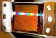
The team has produced CAT gratings larger than 30 x 30 mm2 that have shown absolute diffraction efficiency (i.e., the percentage of X-rays that are diffracted and not lost, and can be used for spectroscopy) over 30% in the soft X-ray band (Chandra grating efficiency is in the range of 1-10%). The team has built small arrays of aligned CAT gratings and a prototype CAT grating spectrograph using NASA GSFC X-ray-focusing mirrors that has demonstrated spectral resolving power (the ability to distinguish between similar wavelengths) greater than 10,000—which is over ten times better than that of Chandra.
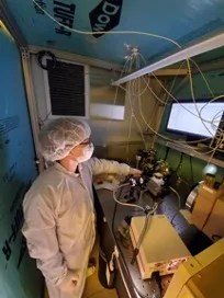
So far, all of these CAT gratings have been made with a painstaking and highly manual “beaker and tweezer” approach in MIT student clean rooms—an effort that typically renders one grating from a 100 mm SOI wafer. However, a flight X-ray grating spectrograph needs thousands of square centimeters of grating area, which means hundreds of gratings. The MIT researchers, in collaboration with the Arcus Grating Explorer team (PI Randall Smith, Smithsonian Astrophysical Observatory) and MIT Lincoln Labs, are currently developing manufacturing methods that would allow high-volume production using 200 mm SOI wafers and commercial optical projection lithography stepper/scanner tools. The successful high-volume fabrication of CAT gratings could provide this enabling technology at affordable cost and short schedule for potential pathbreaking high-resolution X-ray spectroscopy missions such as Arcus, soft X-ray spectro-polarimetry missions such as REDSoX, and for a next-generation grating instrument on a future mission concept such as Lynx.
The team continues to advance CAT grating spectrometer Technology Readiness Levels (TRLs) and improve the performance of fabricated gratings, in particular by making deeper grating bars and optimizing the strength and transmission of the support mesh. Team members are also developing improved metrology, alignment, and assembly tools that will be critical in a flight program.
PROJECT LEAD
Dr. Mark Schattenburg and Dr. Ralf Heilmann, Massachusetts Institute of Technology
SPONSORING ORGANIZATION
Astrophysics Division‘s APRA and SAT Programs


