Chapter 11: Onboard Systems
Page One | Page Two | Page Three | Page Four
Temperature Control Subsystems
An interplanetary spacecraft is routinely subjected to extremes in temperature. Both the Galileo and Cassini spacecraft were designed for primary missions deep in the outer solar system, but their gravity-assist trajectories kept them in close to the Sun for a long time. They had to be able to withstand solar effects much stronger than here on Earth as they flew by Venus during early cruise. And for their missions at Jupiter and Saturn, their design had to protect them from extreme cold.
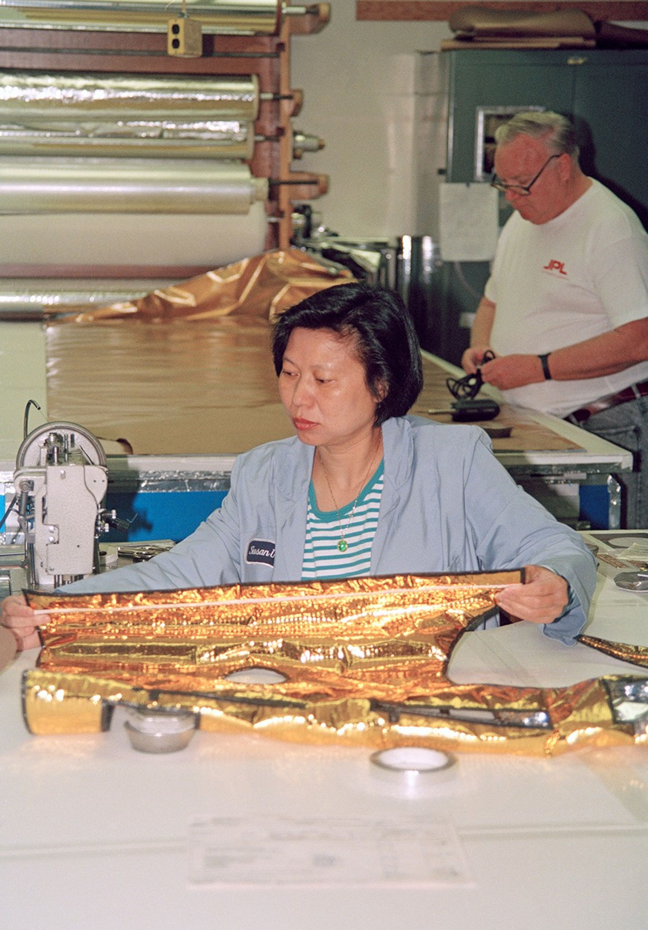
Passive thermal control is obtained with multi-layer insulation, MLI, which is often the most visible part of a spacecraft. White or gold-colored thermal blankets reflect infrared, IR, helping to protect the spacecraft from excess solar heating. Gold is a very efficient IR reflector, and is used to shade critical components.
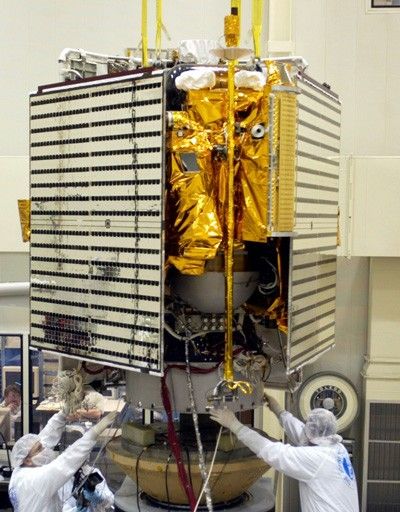
The image above shows the Cassini spacecraft being fitted with its multilayer insulation thermal blanketing.
Their gold color results from a reflective silvery aluminum coating behind sheets of amber colored Kapton material. MLI reflects Sunlight to shade the spacecraft against overheating, and retains internal spacecraft heat to prevent too much cooling.
Optical solar reflectors (OSRs, also called Thermal Control Mirrors), which are quartz mirror tiles, are used for passive thermal control on some spacecraft, to reflect Sunlight and radiate IR. They were used extensively on Magellan, operating at Venus's distance from the Sun (0.72 au).
Messenger, the Mercury orbiter spacecraft, which had to endure operating only 0.38 AU from the Sun, employed 70 percent OSRs and 30 percent solar cells on its solar panels, seen folded in this image of the Messenger spacecraft.
Its sunshade, made of ceramic cloth, kept the spacecraft at room temperature despite sunlight 11 times more intense at Mercury's distance than at Earth's.
Active thermal control components include autonomous, thermostatically controlled resistive electric heaters, as well as electric heaters that can be commanded on or off from Earth.
Electrical equipment also contributes heat when it is operating. When the equipment is turned off, sometimes a replacement heater is available to be turned on, keeping the equipment within its thermal limits.
Sometimes radioisotope heater units (RHUs) are placed at specific locations on the spacecraft.
Temperature sensors are placed at many locations throughout the spacecraft, and their measurements are telemetered to thermal engineers.
They can command heaters as needed, and recommend any needed modifications to spacecraft operations to make sure no thermal limits are violated.
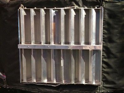
Louvers, which on some spacecraft may be counted under the mechanical devices subsystem, help minimize electrical power used for heaters to maintain temperature. They can help adapt to changes in the environment.
Louvers vary the angle of their blades to provide thermal control by changing the effective emission of a covered surface.
The louvers are positioned by bi-metallic strips similar to those in a thermostat. They directly force the louvers open when internal temperatures are high, permitting heat to radiate into space. Cold internal temperatures cause the louvers to drive closed to reflect back and retain heat.
Active cooling systems, such as refrigeration, are generally not practical on interplanetary spacecraft. Instead, painting, shading, and other techniques provide efficient passive cooling.
Internal components will radiate more efficiently if painted black, helping to transfer their heat to the outside.
For an atmospheric spacecraft, the searing heat of atmospheric entry is typically controlled by an aeroshell whose surface may be designed to ablate or simply to insulate with high efficiency. After entering the atmosphere, the aeroshell is typically jettisoned to permit the spacecraft to continue its mission.
Micro-meteoroid Protection
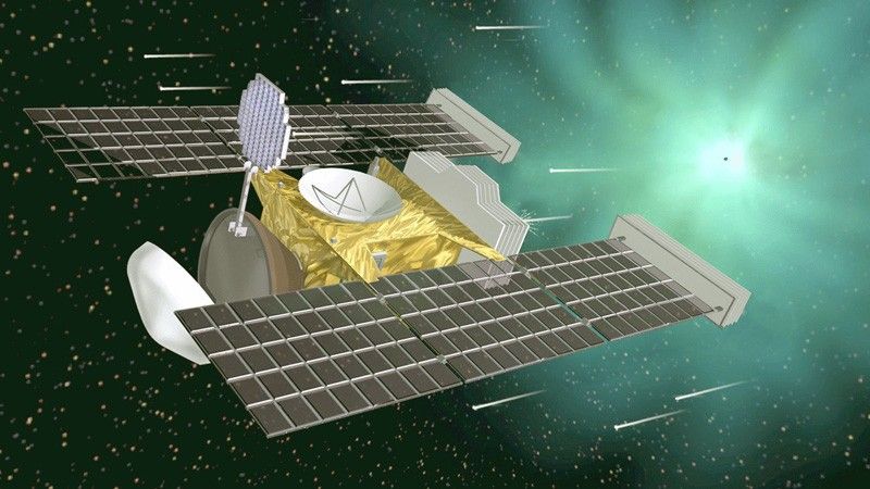
Multi-layer thermal insulation blankets also provide some protection against micro-meteoroid impacts. They are made with Kapton, Kevlar, or other fabrics strong enough to absorb energy from high-velocity micro-meteoroids before they can do any damage to spacecraft components. Impact hazards are greatest when crossing the ring planes of the Jovian planets. Voyager recorded thousands of hits in these regions, as did Cassini crossing Saturn's ring plane, fortunately from particles no larger than smoke particles. Spacecraft sent to comets, such as Giotto and Stardust, carry massive shields to protect from hits by larger particles.
Propulsion Subsystems
Launch vehicles, addressed in Chapter 14, provide the massive propulsion needed to leave Earth and start out on an interplanetary trajectory. Once the few minutes of launch acceleration are over, a spacecraft uses its smaller-capacity on-board propulsive devices to manage three-axis stability or control its spin, to execute maneuvers, and to make minor adjustments in trajectory. The more powerful devices are usually called engines, and they may provide a force of several hundred Newtons. These may be used to provide the large torques necessary to maintain stability during a solid rocket motor burn, or they may be the only rockets used for orbit insertion.
Smaller devices, generating between less than 1 N and 10 N, are typically used to provide the delta-V for interplanetary trajectory correction maneuvers, orbit trim maneuvers, reaction wheel desaturation maneuvers, or routine three-axis stabilization or spin control. Many of the activities of propulsion subsystems are routinely initiated by AACS. Some or all may be directly controlled by or through CDS.
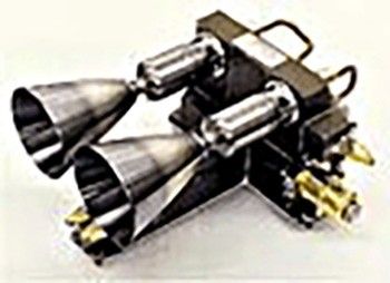
This photo shows one of the Magellan spacecraft's four rocket engine modules, that were mounted on struts not unlike Cassini's, pictured below. Each module has two 445-N engines, one gold-colored 22-N thruster, and three gold colored 1-N thrusters. The 445-N engines were aimed aft for large midflight course corrections and orbit-trim corrections, and for controlling the spacecraft while its solid rocket motor burned during Venus orbit insertion.
The 22-N thrusters kept the spacecraft from rolling during those same maneuvers. The 1-N thrusters were used for momentum wheel desaturation and other small maneuvers. Additional examples of thrusters can be found at this supplier's website.
Other components of propulsion subsystems include propellant tanks, plumbing systems with electrically or pyrotechnically operated valves, and helium tanks to supply pressurization for the propellant. Some propulsion subsystems, such as Galileo's, use hypergolic propellants--two compounds stored separately which ignite spontaneously upon being mixed in the engines' or thrusters' combustion chamber.
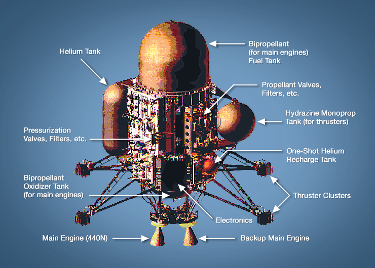
Other spacecraft use hydrazine, which decomposes explosively when brought into contact with an electrically heated metallic catalyst within the engines or thrusters. Cassini, whose propulsion system is illustrated below, uses both hypergolics for its main engines and hydrazine monopropellant for its thrusters.
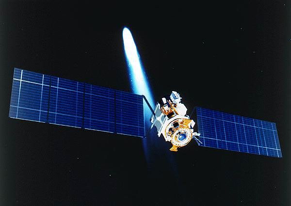
The Deep Space 1 spacecraft was a pioneer in the use of ion-electric propulsion in interplanetary space. With their high specific impulse (due to high nozzle exit velocities), ion engines can permit spacecraft to achieve the high velocities required for interplanetary or interstellar flight. The Dawn spacecraft is also equipped with ion thrusters, which have been used to propel Dawn from its first target, the asteroid Vesta, to another asteroid, Ceres.
An ion engine functions by taking a stable, noble gas such as xenon, and ionizing it (removing electrons from the atoms) to make it responsive to electric and magnetic fields. Then the ions are accelerated to extremely high velocity using electric fields and ejected from the engine. Electrical power comes from arrays of photovoltaic cells converting Sunlight, so the technology is also called solar-electric propulsion.
The act of ejecting mass at extremely high speed provides the classical action for which the reaction is spacecraft acceleration in the opposite direction.
The much higher exhaust speed of the ions compared to chemical rocket exhaust is the main factor in the engine's higher performance.
The ion engine also emits electrons, not to take advantage of accelerating their tiny mass, but to avoid building a negative electric charge on the spacecraft and causing the positively charged ion clouds to follow it.
Mechanical Devices Subsystems
A mechanical devices subsystem typically supplies equipment to a spacecraft that deploys assemblies after launch. Often it provides motion that can be initiated, but once initiated is not controlled by feedback or other means. Some of these are pyrotechnically initiated mechanisms (pyros). These devices may be used to separate a spacecraft from its launch vehicle, to permanently deploy booms, to release instrument covers, to jettison an aeroshell and deploy parachutes, to control fluid flow in propulsion and pressurization systems, and to perform many other such functions.
While pyro devices are lightweight, simple and reliable, they have drawbacks including their "one-shot" nature, mechanical shock, and potential hazards to people handling them. Mars Pathfinder depended on 42 pyro device events during atmospheric entry, descent and landing. Each Mars Exploration Rover spacecraft, Spirit and Opportunity, fired 126 pyro devices during Mars atmosphere entry, descent, and landing. A launch vehicle may depend on a hundred or more pyro events during ascent.
Prior to initiating or "setting off" a pyro device, an assembly in the electrical power subsystem, typically called a pyrotechnic switching unit (PSU), may be commanded to operate, charging a capacitor bank that can provide the spike of high current the device needs to fire, protecting the main bus from a momentary power drain. Pyro devices typically used on a spacecraft include pyro valves, "explosive" bolts, zip cord, cable cutters, and pin pullers. "Explosive" bolt is a misnomer since modern devices are designed to separate with little mechanical shock and no stray particle release.
It may be informative to visit a pyrotechnic device supplier's website.
Alternative technologies are becoming available to perform some of the tasks traditionally performed by pyro devices. For example paraffin actuators perform mechanical functions when electrically heated.
Block Diagram Illustration
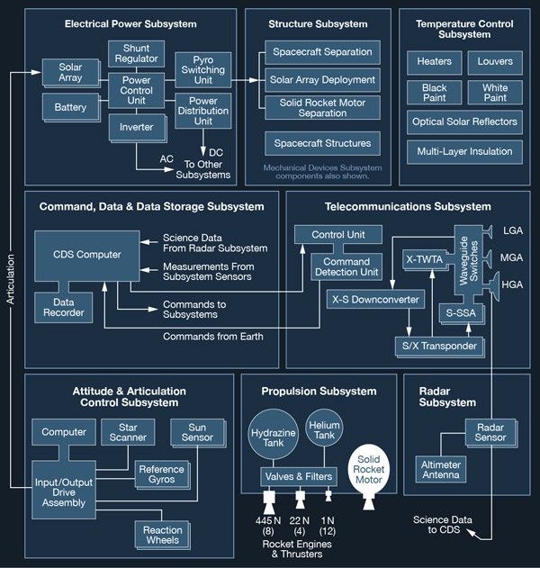
Linked here is a block diagram that illustrates how an interplanetary Space Flight System functions, using the Magellan spacecraft, which combined many of the subsystems discussed in this chapter. Magellan's mission succeeded in obtaining high resolution data from the entire surface of Venus in the early 1990's. The spacecraft carried only one science instrument, the Radar, to penetrate Venus's cloud cover. Otherwise, the spacecraft's subsystems are representative of those found on many other spacecraft.
Boxes within the diagram are shown double or triple to indicate the presence of two or three units of the same name. The numbers 12, 4, and 8 below the rocket engines indicate the quantity of each kind installed.
Redundancy and Flexibility
The hallmark of modern automated spacecraft is the ability to maintain or restore functionality after component failures. Components fail unexpectedly during the life of a mission. Most components upon which the success of the mission depends have redundant backups, and the means to reroute functional flow to accommodate their use either autonomously or via commanding in real time. Spacecraft such as Voyager, Galileo, Ulysses, and Pioneer, have enjoyed greatly extended missions, returning valuable science data long after their primary missions have been completed. This is due entirely to the on-board availability of redundant transmitters, receivers, tape recorders, gyroscopes, and antennas. The ability to modify on-board flight software has allowed them the flexibility to increase and extend functionality based on newly conceived techniques.
Advanced Technologies
Ongoing research at JPL and other institutions is producing new technologies useful for less costly and more capable, more reliable and efficient spacecraft for future space missions. Advances in such areas as spacecraft power, propulsion, communications, navigation, data handling systems, pointing control, and materials is expected to increase by many times the potential science returns from future missions. Here are a few of the many promising technologies being developed:
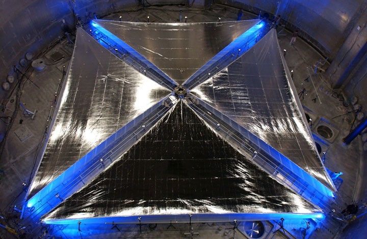
Solar sails, which use solar radiation pressure in much the same way that a sailboat uses wind, promise to provide the means for high-speed interplanetary or interstellar propulsion. Here are some interesting solar-sailing links:
Telecommunications systems are being developed to operate in K and Ku bands, higher frequencies than the current S- and X-band systems.
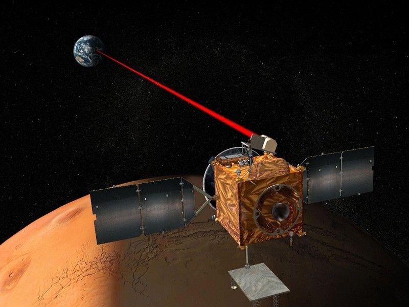
Laser telecommunications systems are also being explored which modulate data onto beams of coherent light instead of radio. Among the advantages to laser telecommunications are low power consumption, much higher data rates, and reduced-aperture Earth stations. The pointing requirements for laser communication are much more stringent than for microwave radio communication. During Galileo's Earth-2 flyby en route to Jupiter, JPL succeeded in transmitting laser signals to Galileo, which received them as points of light detected by the Solid State Imaging System (SSI).
Interferometry will be a technology that enables science observations to achieve immense improvements in spatial resolution and sensitivity. Spaceborne radio telescopes, infrared telescopes and visible-light telescopes will be flown in exacting formation to synthesize large apertures for many different types of investigations in astronomy, astrophysics and cosmology. These instruments are expected to eventually be able to image planets around neighboring stars.
JPL has many planned and proposed missions which will take advantage of advanced technologies.

